

I was once asked if I would be able to make a bike with an oversize bottom bracket and full internal cable routing, amongst other things. Although this project came to nothing it had been on my mind for some time to use a T47 bottom bracket, my only personal reason for this would be that it gives the space to potentially run cables and cable guides right through. I have never been keen on partial internal gear cable routing which always looks untidy, and I have never been happy with the idea of drilling holes in chain stays, though I now do this regularly.
I would choose T47 over press fit, do I need to say why, though I did make a press fit bottom bracket shell for a balance bike and it was OK as far as I am aware.
Ceeway do stock PF30 press fit bottom bracket shells, which appear to be the same dimensions as T47, so I presume it would be feasible to cut threads in a PF30 to make a T47. Paragon in the USA make both Stainless and Plain steel T47’s and Bear frame supplies do plain steel ones but both were out of stock at the time I looked. Reynolds do also now supply them. The upshot of this is I decided to make my own, how difficult could this be, well a lot more difficult than anticipated, but I got there.
T47 dimensions are a 46mm internal bore, a 47mm diameter metric thread with a 1.0mm pitch; devised, I believe, by Chris King.
I bought enough steel tubing for a couple of plain steel and stainless steel shells. Selection of raw materials is limited to availability from the suppliers who are prepared to sell small quantities. Paragon use 17/4 stainless steel, which is also used by manufacturers Reynolds and Columbus for their stainless bottom bracket shells and possibly head tubes. This isn’t readily available so I had to settle for 304 stainless steel welded tube 50.8mm o.d. with a 3mm wall. This costs less than £3 for material for one shell, plus postage. For the plain steel shells I chose CDS steel tube (stands for cold drawn seamless) 50.8 o.d. with a 6.4mm wall. It is a form of mild steel. Due to the weight of metal you are buying the stainless is half the price of the plain steel.
I commenced by turning down the outside of the plain steel tube just far enough to clean the surface, and left the stainless tube outer surface as it was. I cut and faced the tubes to slightly over 68mm and bored out the internal diameters on the lathe to 46mm then put a relief channel in at 15mm to allow to run in a thread I had purchased a surprisingly cheap T47 bottom bracket for test purposes (thank you Merlin Cycles), which has a thread length of 12mm, which I presume must be standard. I then used a single point threading tool to cut the threads, Right and Left, to the 47mm guided by test fitting the previously mentioned bottom bracket cups. I ended up scrapping one of the plain steel shells because the first threading wasn’t up to standard. Of course the threads are cut individually so it is necessary to remove and reverse the shell in the lathe leading to a potential for inaccuracy in alignment. I therefore turned a dummy axle to slide through the inserted cups to ensure the bottom bracket was properly aligned.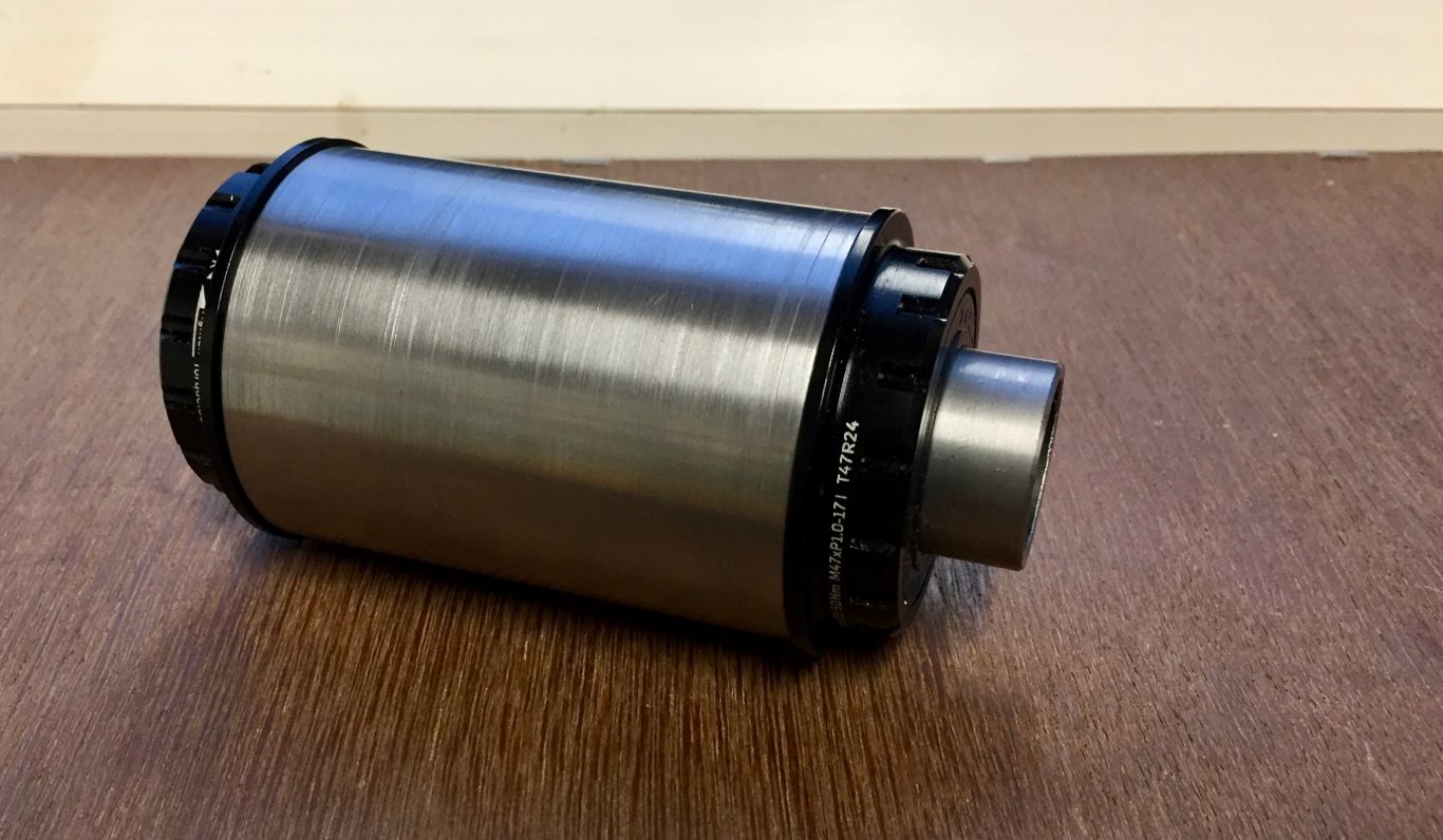
I also mirror polished the stainless shells. This process only reduces the outside diameter from 50.8 to 50.75mm.
The lathe is a relatively quick way to sand down the shells for mirror polishing with emery cloth strips but care needs to be taken.
Another aspect to using a different standard for a component is the extra tooling required, and this is what drives me to make as much of my own as is feasible. A further issue was going to be whether I will need to purchase, or get access to, T47 thread chasers and facers. These seem to be disproportionally more expensive than the usual British standard thread cutters, indeed up to several hundred pounds, not including yet more matching handles. I needed to make some adapters so I can fit the larger bracket shell into my frame building jig. These simply take the form of larger washers to go around the existing bosses. I thought I would try a makeshift heatsink arrangement at the same time so have made the adapters to loosely screw into the shell, rather than just push fit, in the (perhaps vain) hope that they may preserve the threads so no further thread fettling will be required. I used the remaining bit of bronze to fashion a sprung heat sink to slip into the middle of the bottom bracket shell to complete the job. All the commercially available bottom bracket heat sinks I have seen completely occlude the bottom bracket so are not suitable if you wish to do any brazing in the jig as obviously it is held in position by a bolt going through.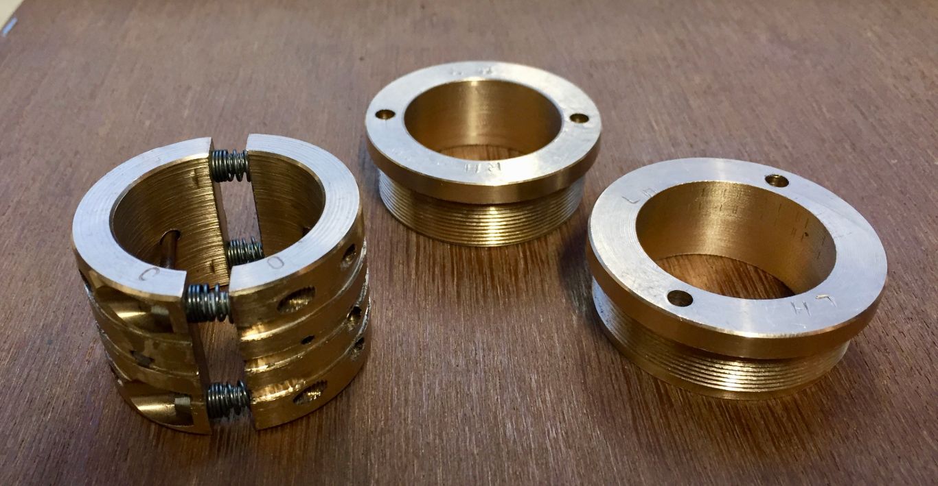
I have now made a frame with one of the T47 bottom brackets above: https://noviceframebuilder.co.uk/techniques/ladies-winter-road-bike-a-step-by-step-guide/. Using the screw in bottom bracket cups to hold the bottom bracket in the jig I managed to preserve the threads such that no chasing or facing was required after the build.
Making your own T47 Bottom Bracket Taps
I decided to try and make some T47 taps. I could not find any information on the construction of similar taps so based the design on existing ones. I have two standard Cyclus taps. The one on the left is a thread chaser, and the one on the right is a thread cutter. They have different bores of 16 mm and 20 mm respectively, so require different handles (Why?). I wanted to re-use my existing handles for the T47 taps and decided on a 16 mm bore which was more practical to make with regards to holding the blanks in the machines.

I purchased a 300 mm length of 2 in diameter Silver Steel from Coventry Grinders for about £80 + postage. They specialise in silver steel and were cheaper than any of my previous steel suppliers. 2 in diameter is also cheaper than 50 mm! You cannot get shorter lengths than 300 mm as the stock comes precision ground. I reckon you can get 8 taps out of this amount. I cut the steel to approx 35 mm lengths. The Cyclus tap is 15 mm deep with a 4 mm shoulder.
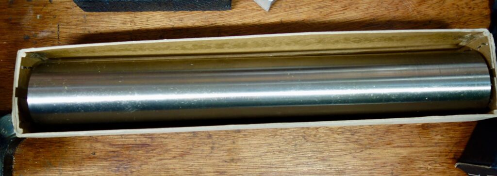
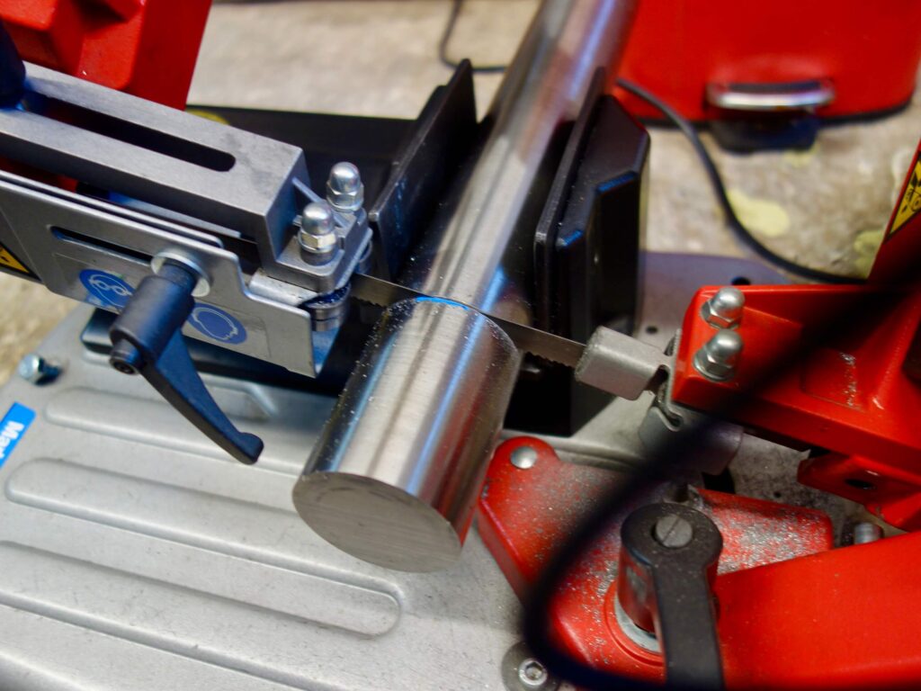
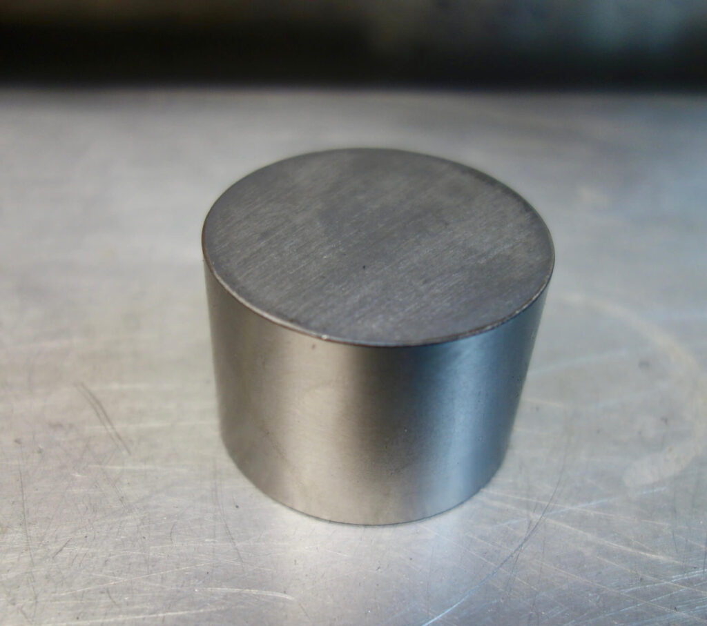
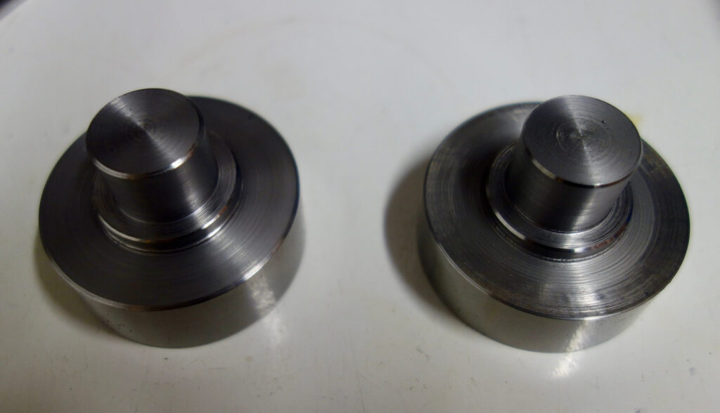
I then set the steel billet in the lathe and faced the end and turned down the surface until it was round and a bit smaller though greater than 47 mm. The piece was then reversed in the chuck and ensuring the portion in the chuck was at least 19 mm the other end was faced and turned down to 28 mm (the width of the shoulder). A length of 4mm was left at this width for the shoulder and the rest turned down to 20 mm. You end up with a blank as shown.
Do’s and Do Not’s
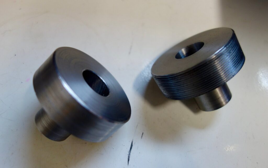
I strongly recommend making these taps singly. Ideally when machining in a lathe you should not remove the piece until all operations are complete as any change of position introduces inaccuracies such as loss of concentricity. When you have the blank as described you can again reverse it in the chuck so it is held by the 20 mm shaft, after which you should not remove it until you have turned the outer diameter to a fraction under 47 mm, bored out the centre, to 16 mm in my case and 19 mm depth, and cut the thread (Right or Left hand). Initially I actually tried to make two blanks from one piece, but found I had to separate them to complete the operations with subsequent loss of concentricity, so these did not make the final results. I bored out the centres with standard drills but finished off with a 16 mm slot mill which produces a better finish, a flat bottom to the hole and is cheaper than a reamer. The face of the tap does need a slight chamfer, say 30 deg, on the edge to enable it to slot into place. The traditional method appears to be to put this chamfer on using a grindstone after the taps have been hardened, though I do not see why you cannot chamfer the edge of the blank piece before cutting the thread. I in fact used both methods and found them equally effective.
Finishing off in a Mill
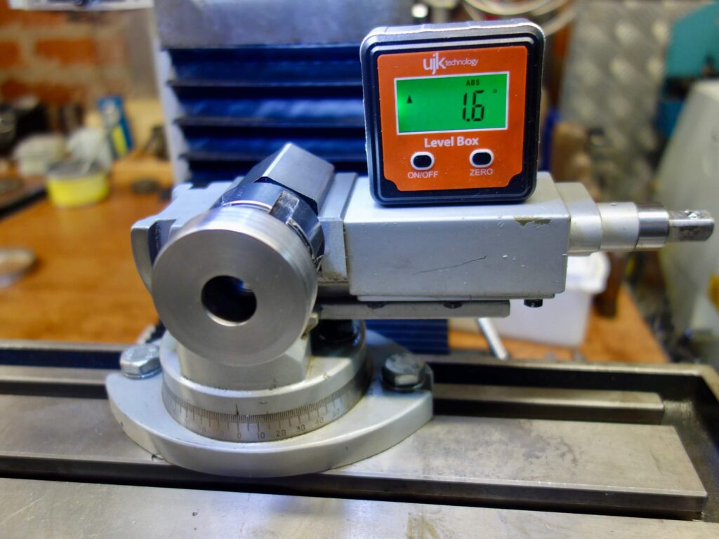
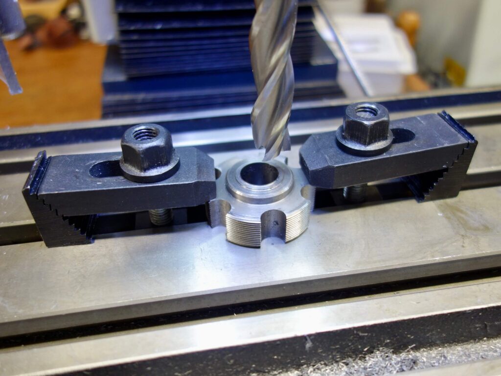
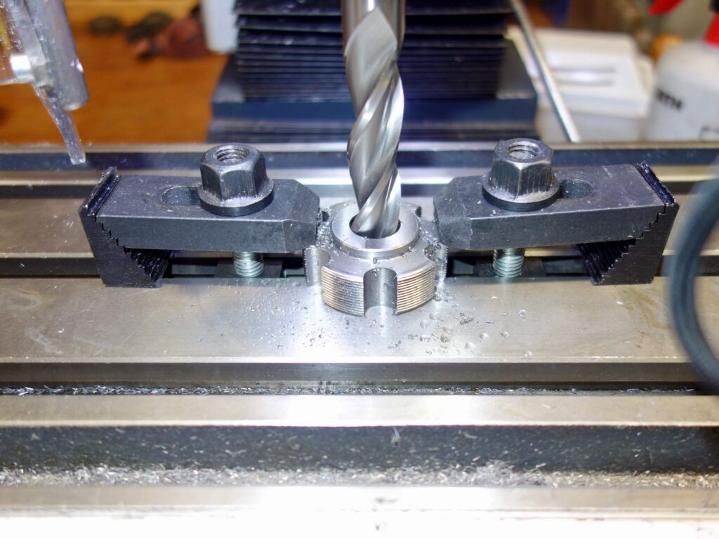
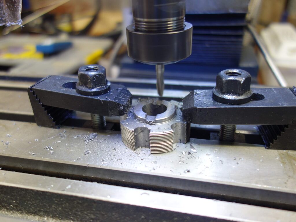
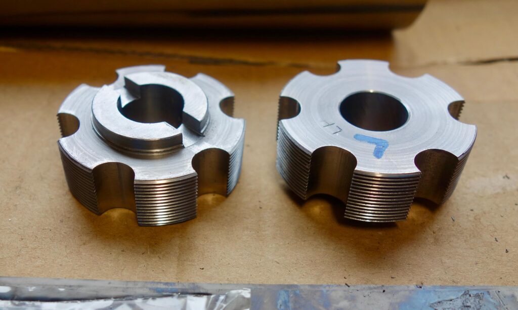
I transferred the workpiece into a hexagonal collet block and set it into a tilting vice. The vice was tilted to to 2 deg give a slight undercut to the cutting edges. This was consistent with the undercut on the Cyclus tools. The collet block can then be rotated to provide 6 grooves to give threaded sections of approx 14 mm, again consistent with the Cyclus chasing tool. I used a 10 mm diameter ball nosed slot mill to depth of 6 mm, which gave a good result with no thread damage. I did use a brand new carbide mill which was very sharp. My first attempt, shown below, used a standard square end mill and did not produce as clean a cut and I was unhappy with the overall result as it looked weaker. I used this tap as a test piece for subsequent operations.
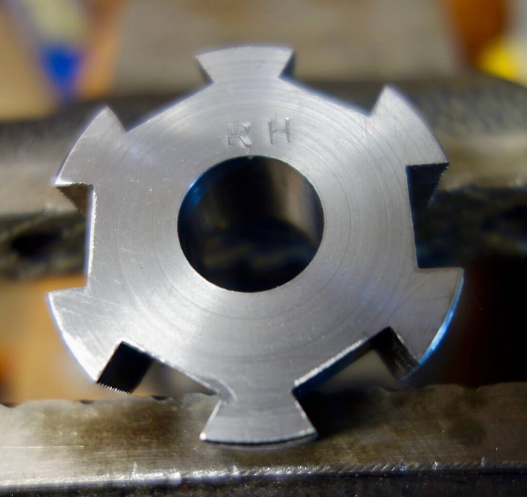
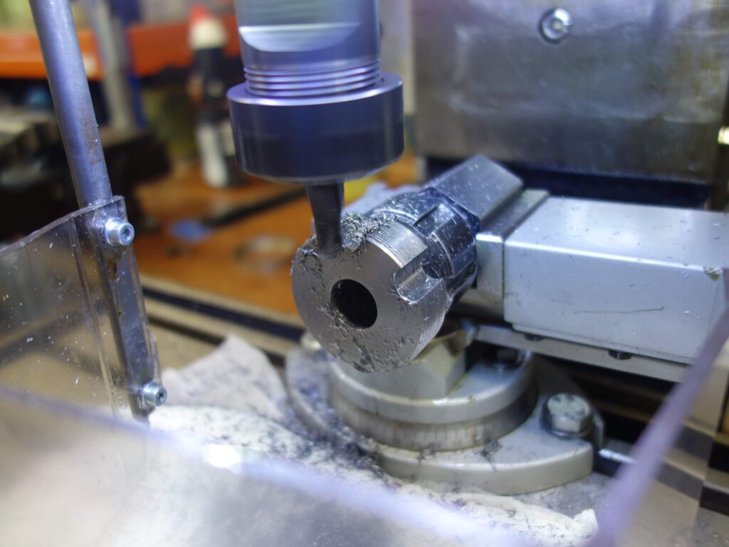
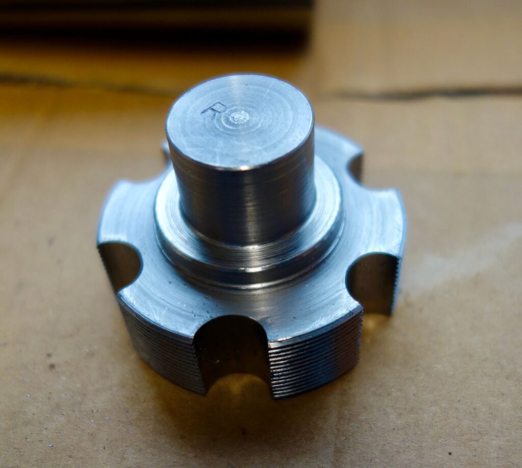
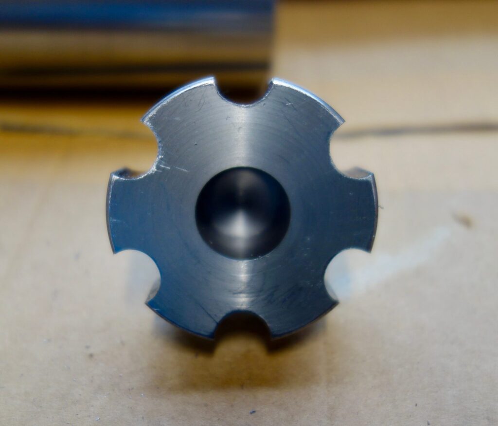
The final machine operation was to cut off the holding shaft, which was easiest to do in the lathe. Then the tap was clamped to the milling table and the surface milled smooth before centring with the 16 mm mill in the centre hole and slot milling the shoulder with a 6 mm slot to locate in the handles.
Hardening (HEAT TREATING)
Hardening Silver steel is a common home workshop practice but still has pitfalls. I used my oxypropane torch with a No 18 tip but I am sure a smaller tip would work. I also used a small brazing hearth purchased from CuP Alloys which helps concentrate the heat and makes the process fairly simple. The principle is to heat the tap up to red heat, often described as boiled carrots, which is above cherry red but below orange. This should be done very slowly. Also a good indication is the loss of magnetism, so have a magnet handy. (I used a flexible pick up magnet). I would get the piece into the red zone then test with the magnet until it is non-magnetic and be wary of heating too much more (i.e overheating). I held this colour temperature for at least 5 minutes, then you need to quench the piece in water. The water should be at room temperature, NOT freezing cold, and you need to agitate the piece in the bucket of water vigorously as it cools as apparently the steam generated around the piece can impair the hardening process. The recommended method is up and down rather than round and round, but I have looked at several recommendations on heat treatment and they do seem to vary a lot. As a reference I have use Tubal Cain’s book: Hardening, Tempering and Heat Treatment, which is widely available from engineering supply companies. A picture appears at the bottom of this page. This gives all the necessary background and insight into the chemistry involved. He does recommend holding the heat based on the size of the piece, but the risk of holding the temperature with a torch is the increased risk of overheating. In fact he does not recommend torch heating at all because of this risk, but ideally using an electric furnace. I have seen these for sale for circa £300, but I think these are the bargain basement versions. I have had no significant problems with using my oxy-propane torch with care so far.
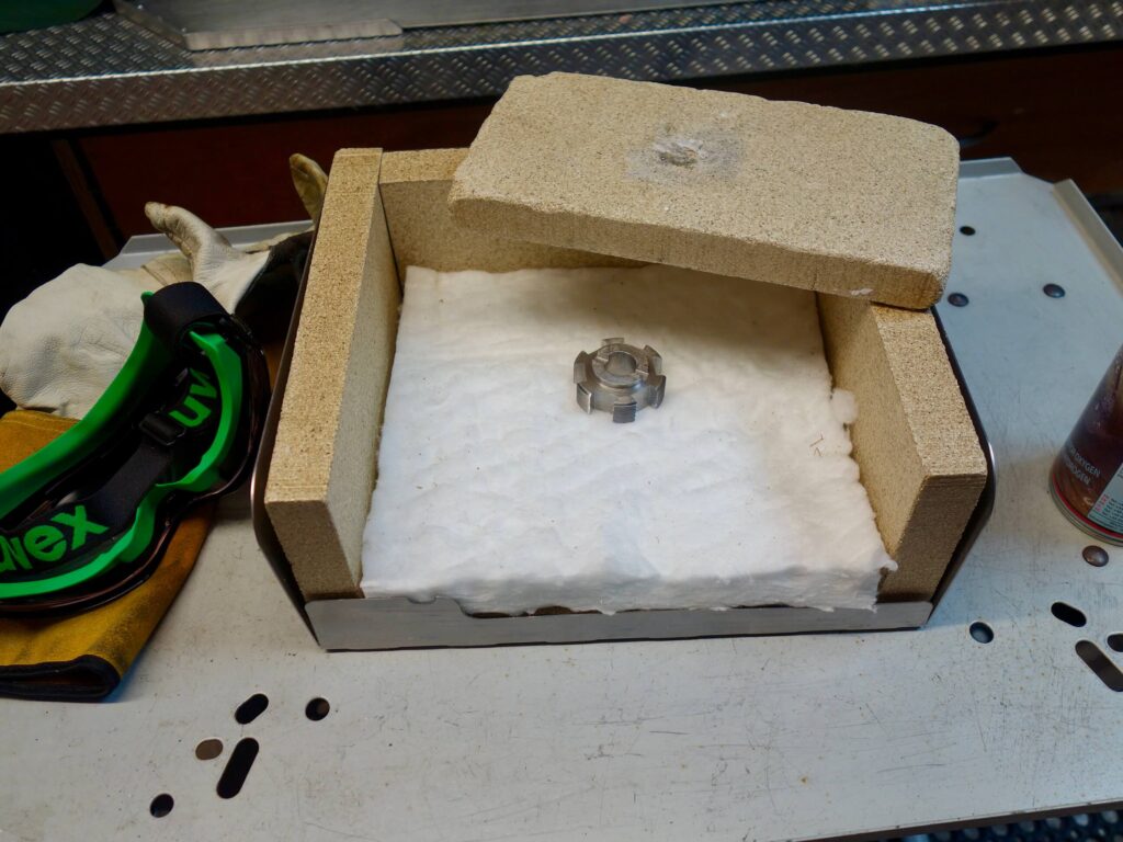
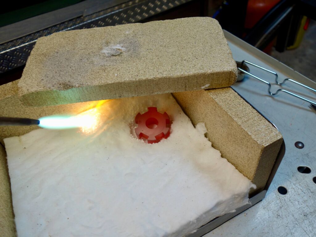
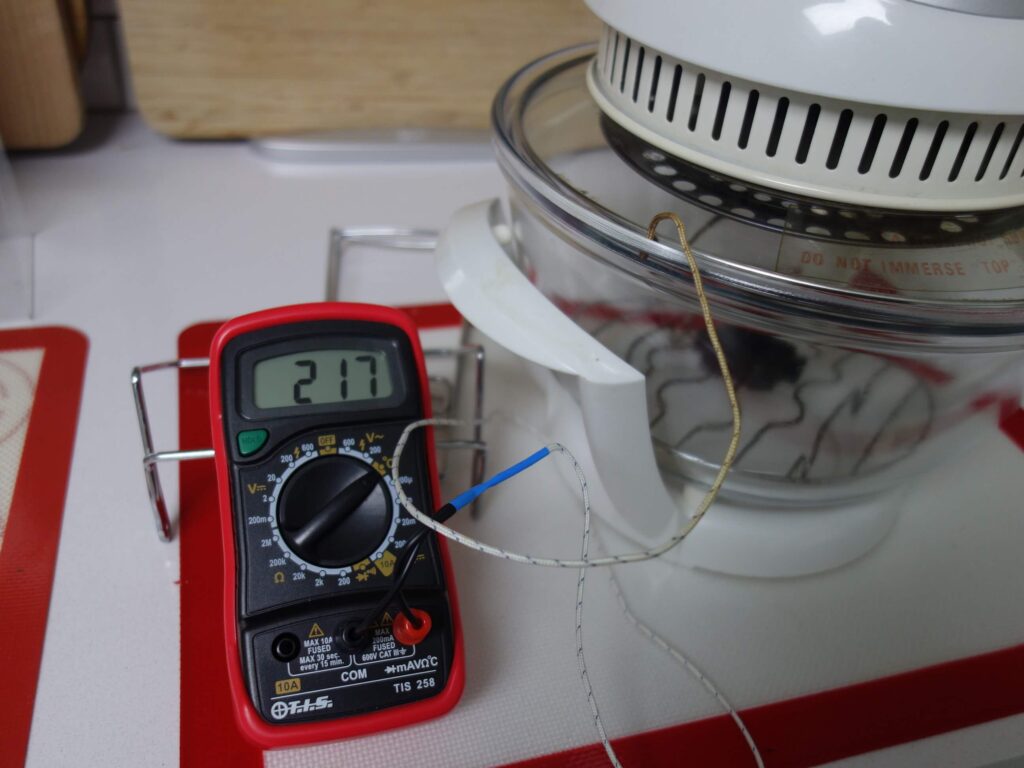
After quenching the piece then needs to be further heat treated because it will be Too Hard and may break in use. You can check if it has hardened by rubbing it with a file which should struggle to make any mark. I heat treated my taps by putting them in a halogen oven turned up to max for an hour. This is at about 200 degrees centigrade. Leave them to cool naturally.
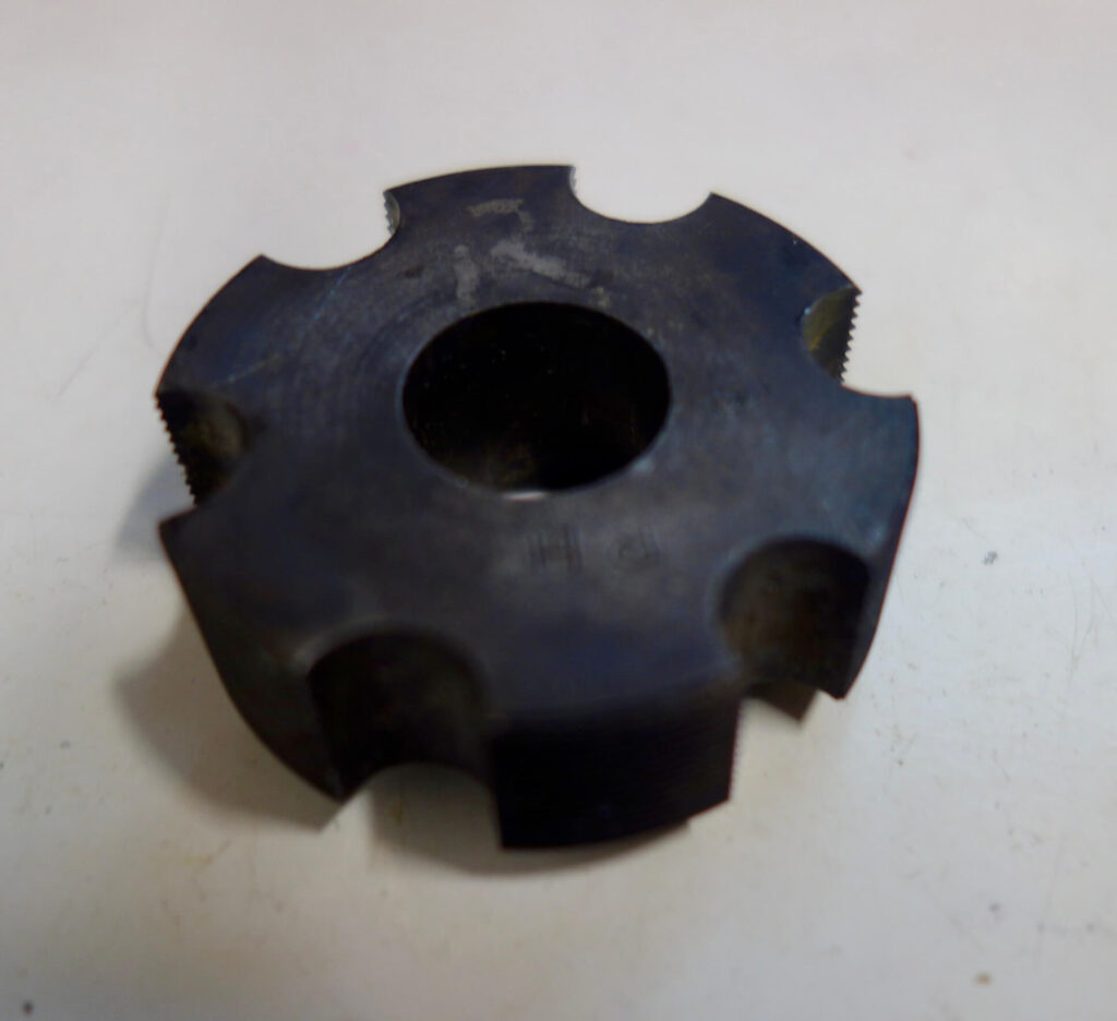
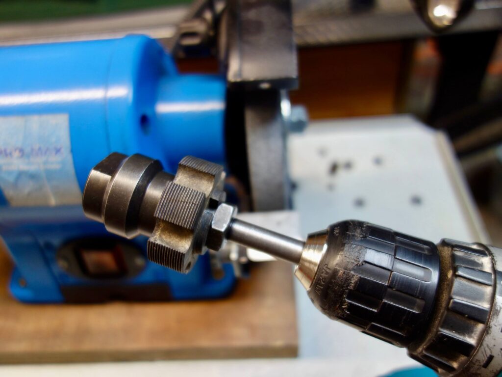
The taps end up black with carbon after heat treatment. I do not think there is a satisfactory way of preventing this if you are using a torch. It is probably part of the surface metal I tried several methods of chemical cleaning and none worked. The only way is to sand them, I used a rotary tool with a sanding disc for all the flat surfaces. A wire brush may clean up the threads but the tap should work anyway. As stated earlier, I had chamfered the leading edge of one tap but needed to grind the other. I did not have a device specifically to rotate the taps against a grindstone so improvised by mounting the tap on a improvised mandrel from bits of Cyclus tooling (to save me having to make something) in a cordless drill and running it at full speed against the grinder. It actually worked very well!
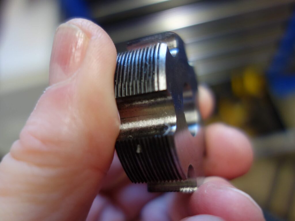
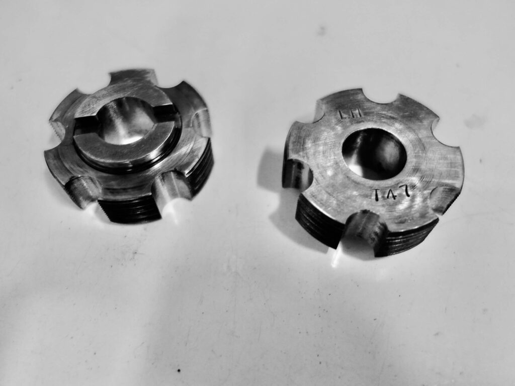
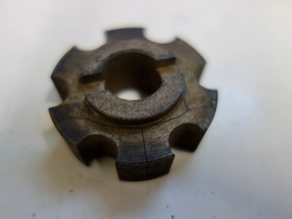
Below is the finished article, I have now chased out several threads and then have worked fine. I have not as yet used them to cut a thread from scratch. Also on the right is the one that went wrong. I think I may have overheated it or used water to quench it that was too cold. You can see it was badly cracked.
The next job is to make a T47 Bottom Bracket Facer.

GOOD NEWS ON COMMERCIAL T47 TAPS
The day after I posted this article I checked the Webbline website to find that they now supply Cyclus T47 taps at a sensible price. These are to fit the Professional handles which are the ones with the 20 mm bore and are retailed at £85, which I assume is for the pair. You can also get the taps with handles for £160.
https://www.webbline.co.uk/shop/spare-bottom-bracket-taps-for-cyclus-pro-bottom-bracket-threading-tool/
https://www.webbline.co.uk/shop/professional-bottom-bracket-threading-tool/
Still no facing tool though.
Making a T47 Facing Cutter
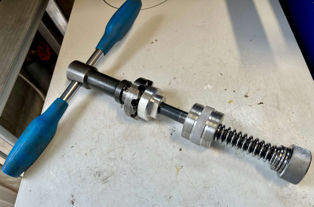
I finally got around to making a T47 Facer. Again I made it to suit my existing CYCLUS facing tool, which has a 16mm threaded rod at its centre. I decided to use a similar design to the head tube facer described elsewhere, as it seemed to work well. A T47 bottom bracket has an outside dimension of 2 inches, which is the same diameter as the largest available diameter of silver steel bar I used for previous projects so I needed something bigger. I opted for the alternative type of tool steel that is readily available i.e Gauge Plate. This comes in a variety of dimensions, but is always rectangular in shape. It also comes with heat treatment instructions on the label. To keep the cost down I bought the smallest size I thought I could get away with a piece 60 mm wide and 30 mm deep. It tends to come in standard lengths of 250 mm.
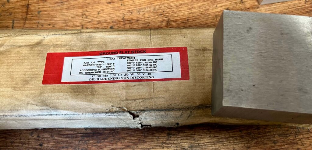
Gauge plate is oil hardening steel and so needs to be quenched in a suitable oil after heat treatment.
Before making the facing cutter I had to make the inserts to hold the cutter in the larger T47 bottom bracket.
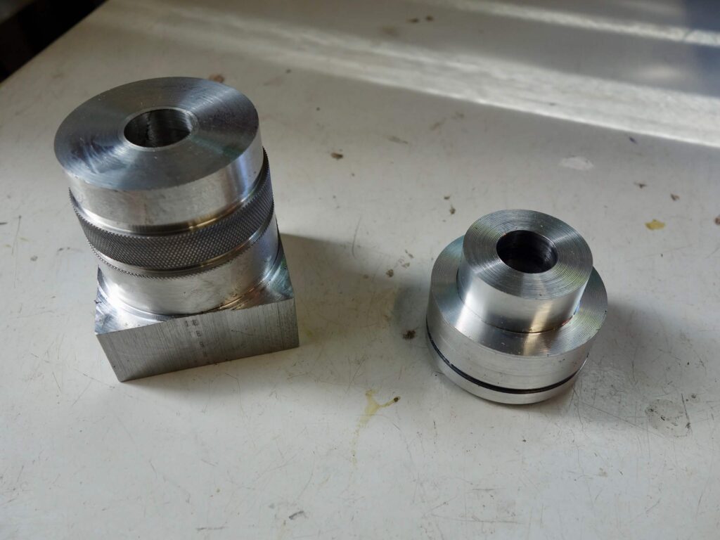
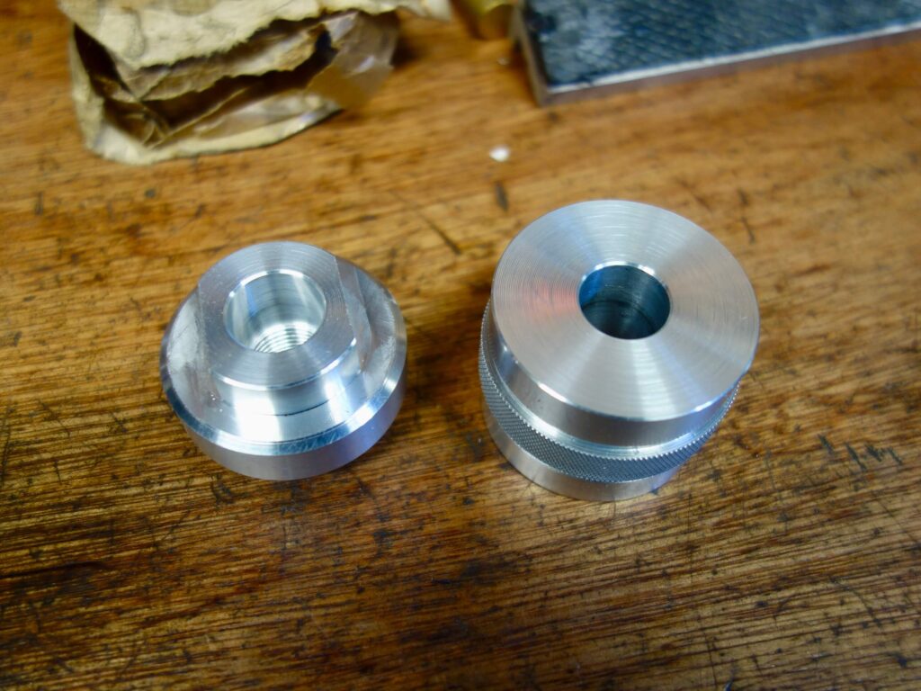
Below are images of the original facer, which, as before I did not think I could replicate; and the BSA inserts to hold the facer in the bottom bracket which would have to be made T47 size.
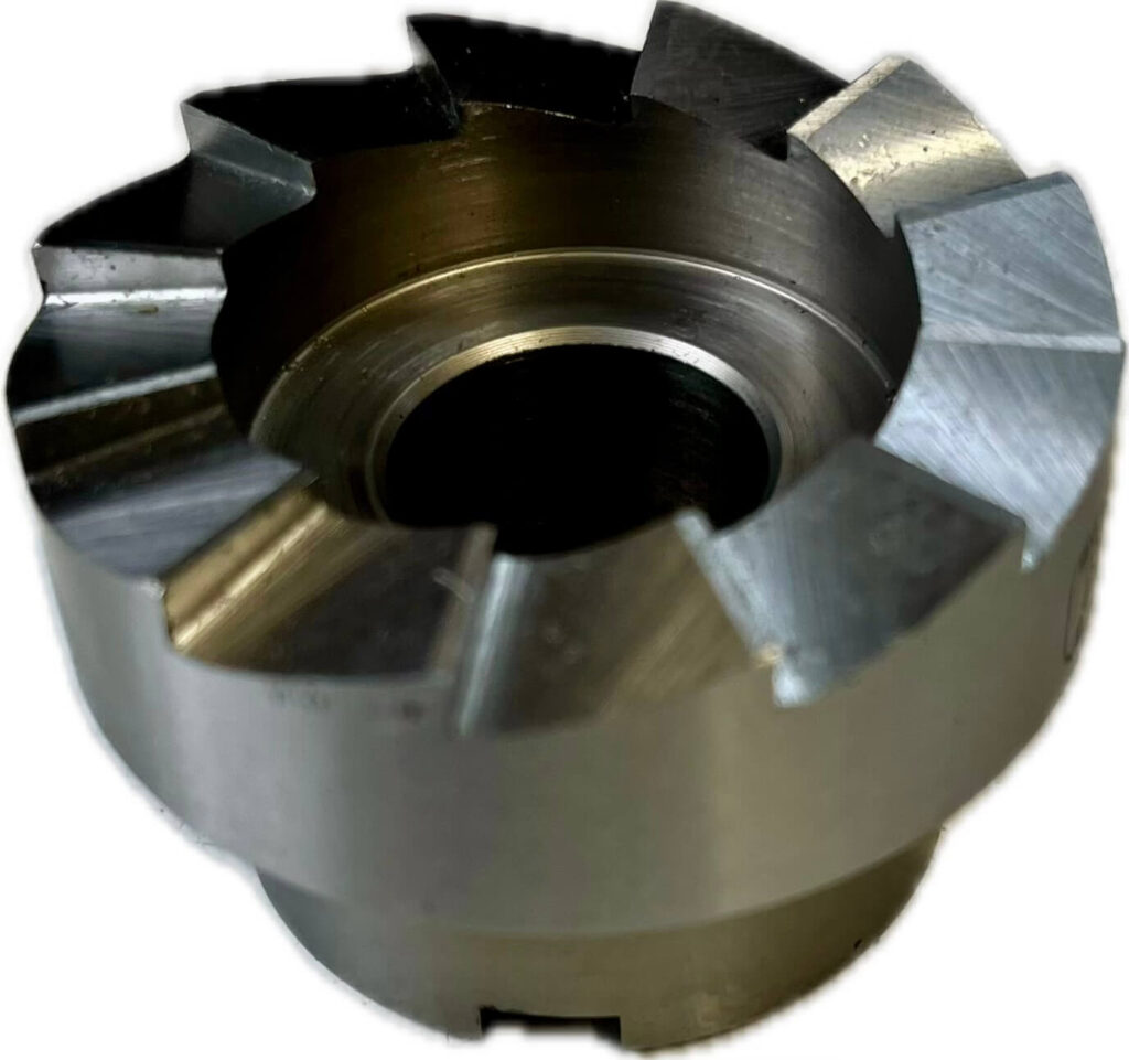
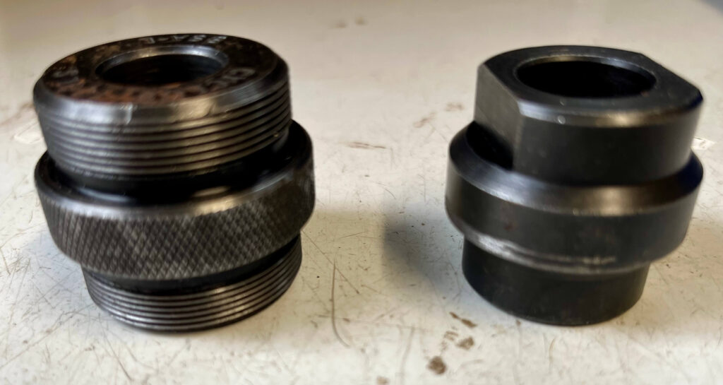
The process I used is described below:
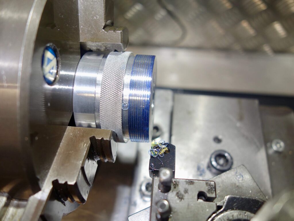
I made the inserts out of aluminium because I had a lot of it available in the correct size, albeit square, so I had to round off the pieces first. A lesson in how to make things difficult for yourself.
For the Facing Cutter:
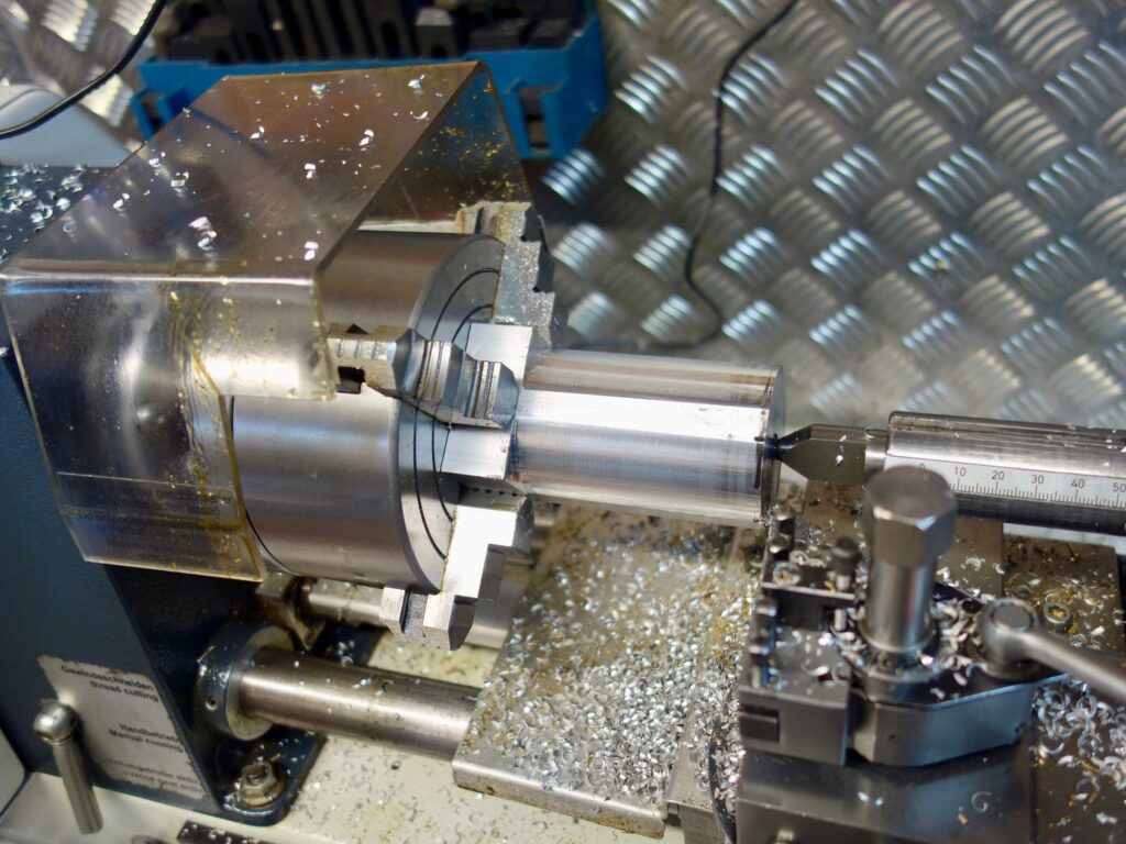
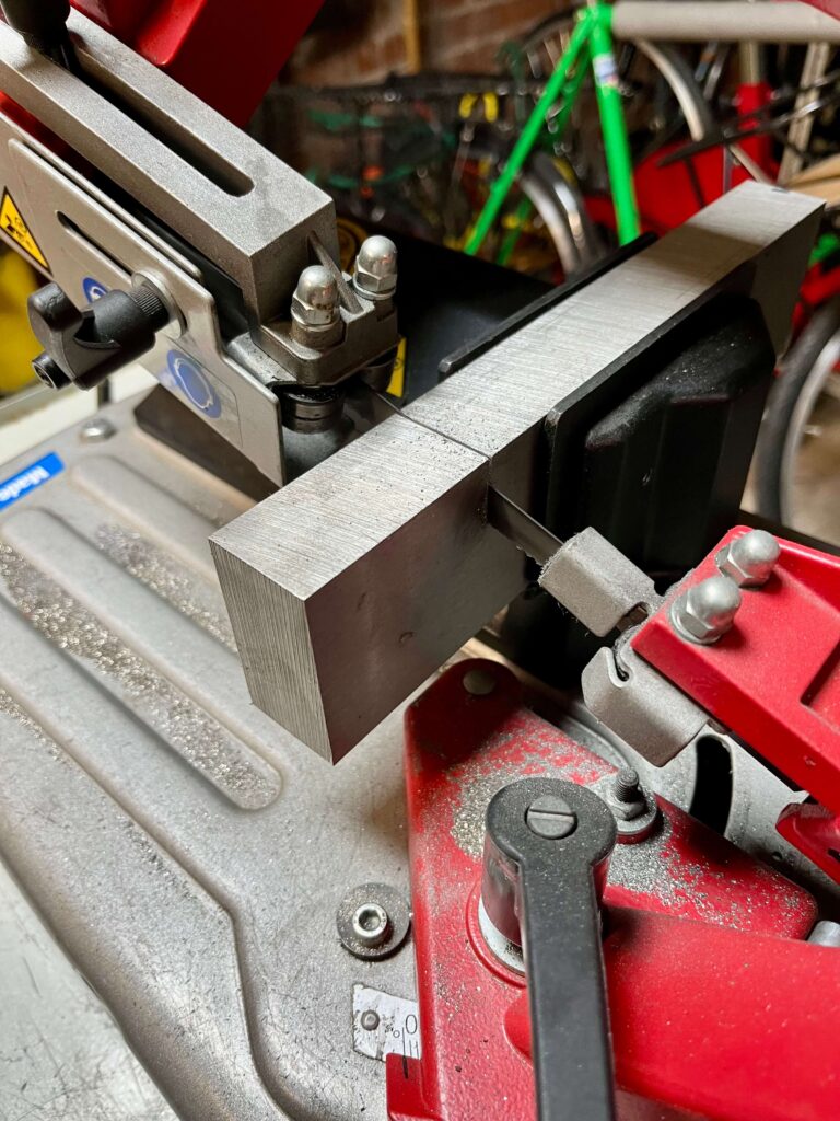
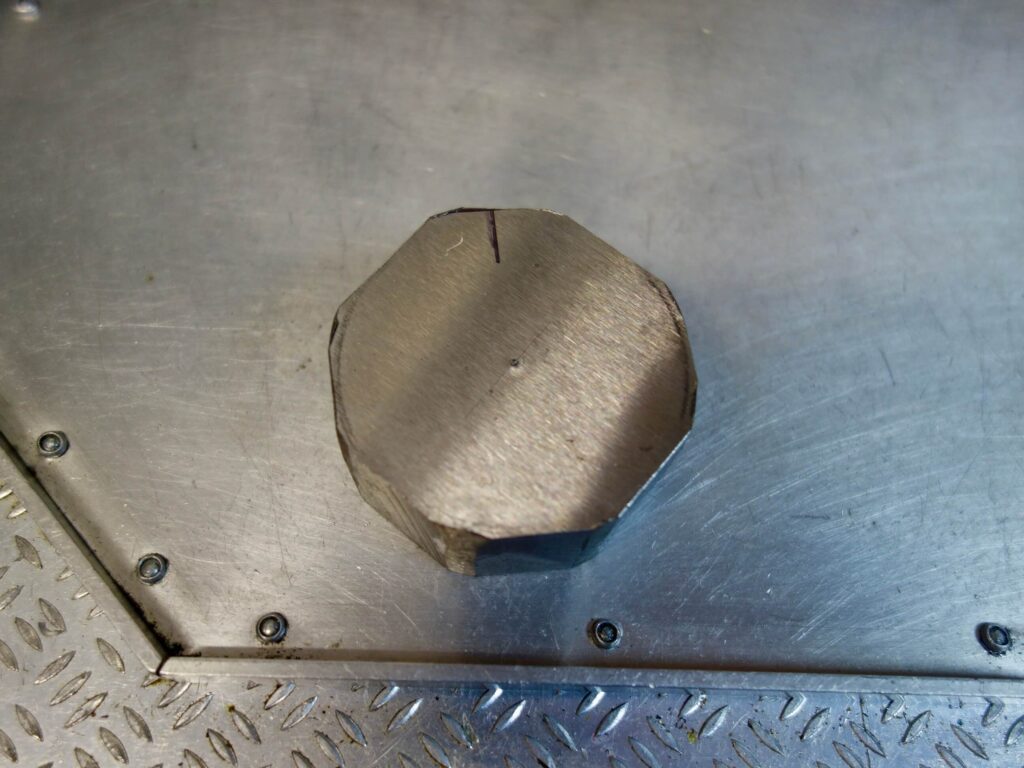
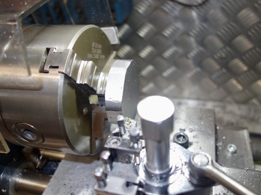
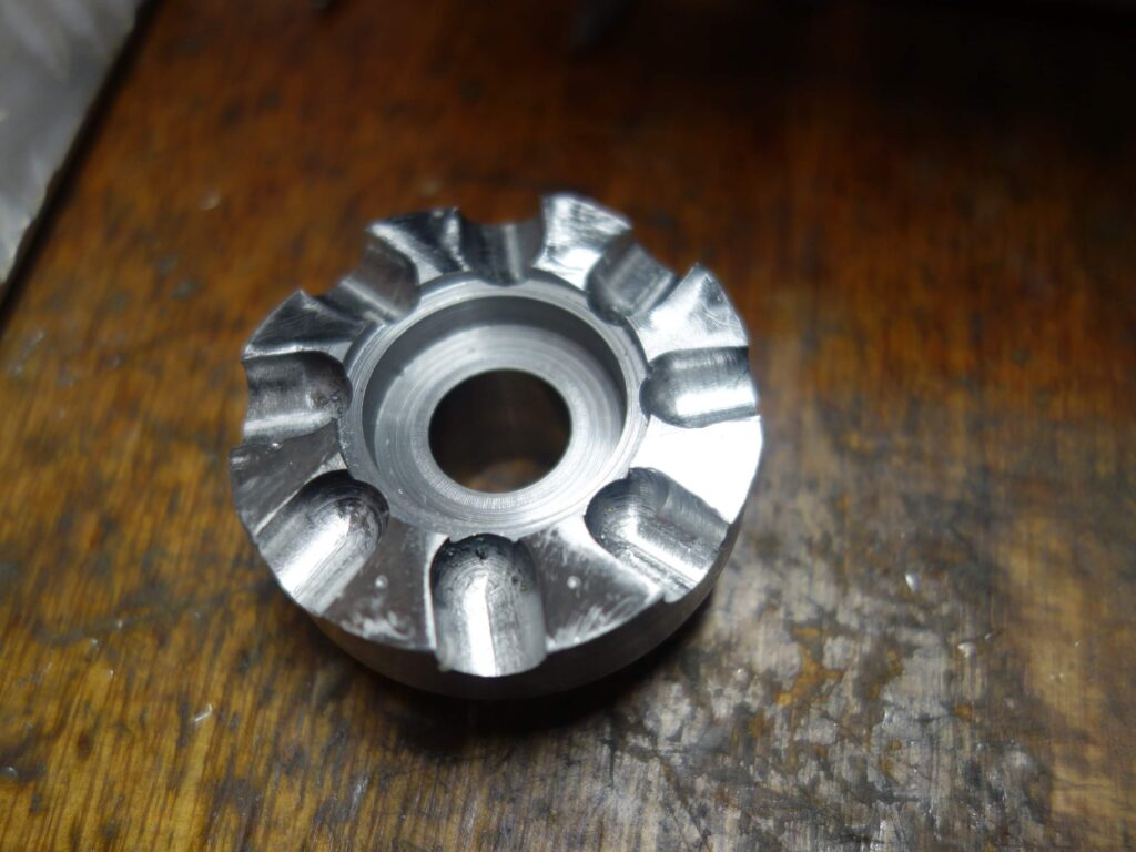
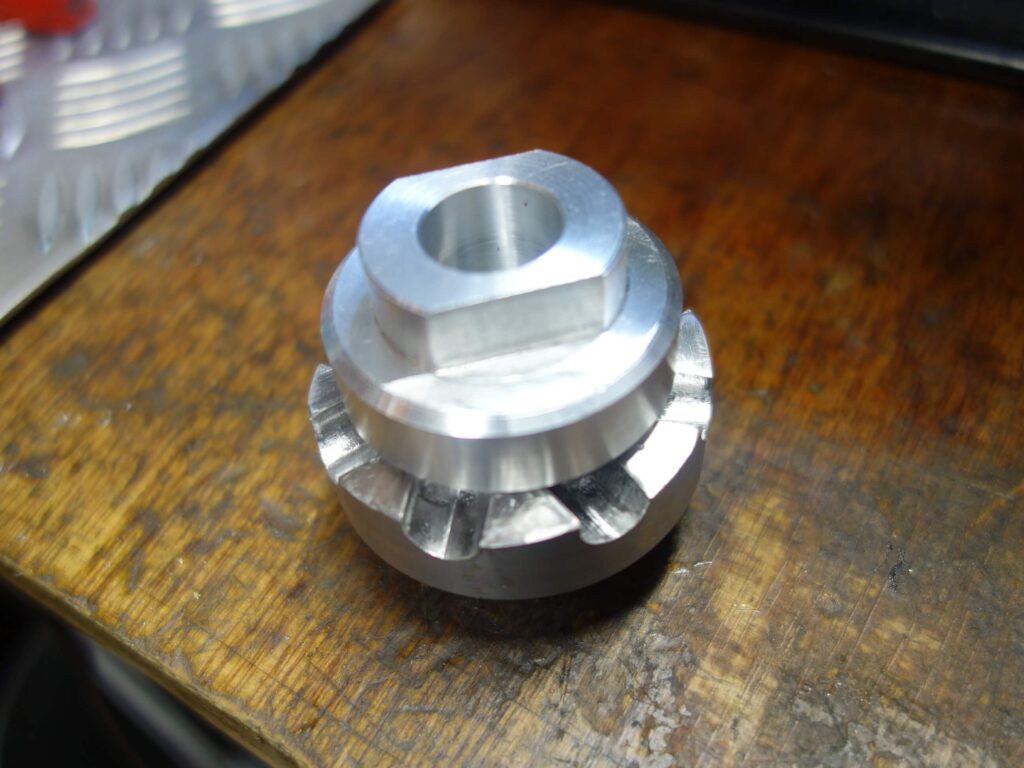
The basic piece of metal was 30mm deep, and I needed to turn half the thickness down to 26mm. This was achieved by measuring and punching the centre of the original square blank. I then used a bench grinder to cut down the corners quickly. I was till able to mount this cut down piece in a four jaw chuck using the punch mark to centre it. It is then possible (just) to turn down 15mm thickness to the required 26mm, then turn it over and round off the remaining 15mm. The final diameter of this was approximately 57 mm. It was then drilled to the required 16mm and a 28mm recess bored in the front. These measurements mimicked the original BSA facing tool.
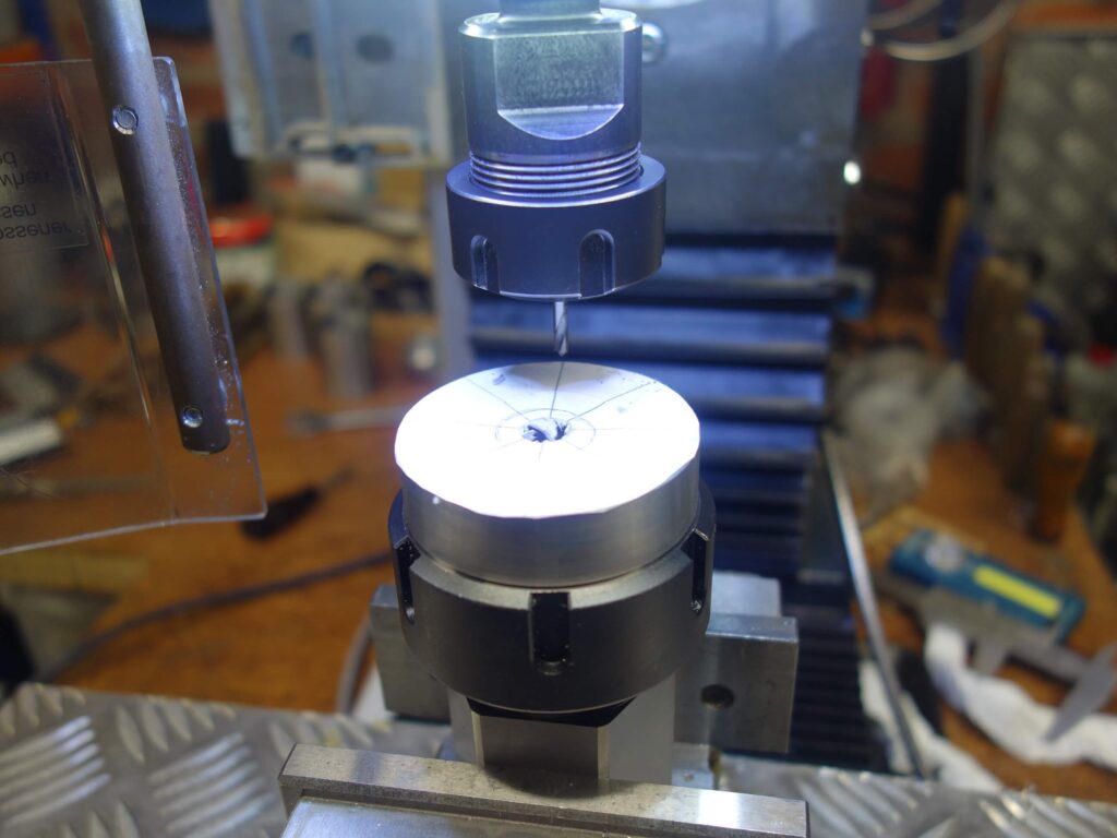
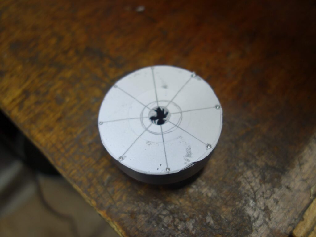
My previous head-tube facer was smaller and had 6 cutting faces. I decided to opt for 8 this time. I made a paper template to mark the 8 divisions and then spot drilled small pits around the edge at each division. As the blank was to be held in the milling machine in a collet block, it meant I could loosen the securing ring and rotate the workpiece the correct distance by lining it up with the spot drill again each time.
I decided to increase the undercut of the cutting edge from the previous 5 deg to 6 deg. So the collet black was clamped in the milling vice at 6 deg. Also in order to angle the cutting edge to replicate the original types, the mill table was moved 5mm from the centre line, which has the effect of offsetting the linear cuts taken on the milling machine which then makes them cut at a slight angle in use.
Cuts milled using a 5mm ball nose mill to a depth of 6mm.
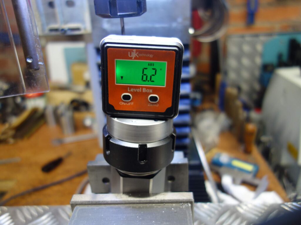
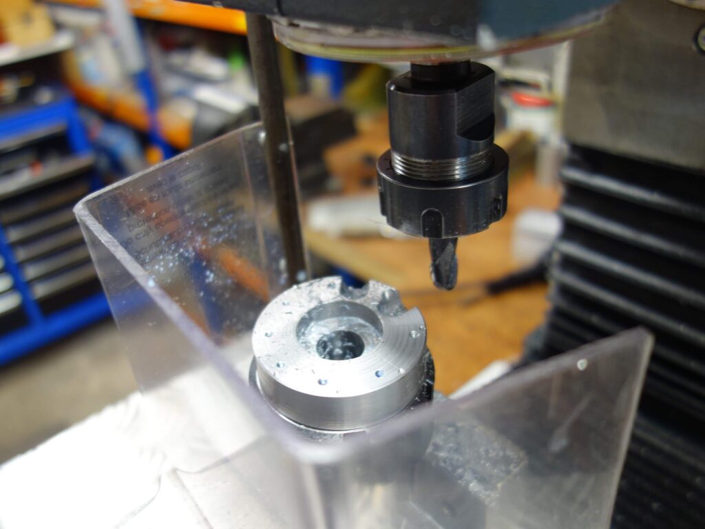
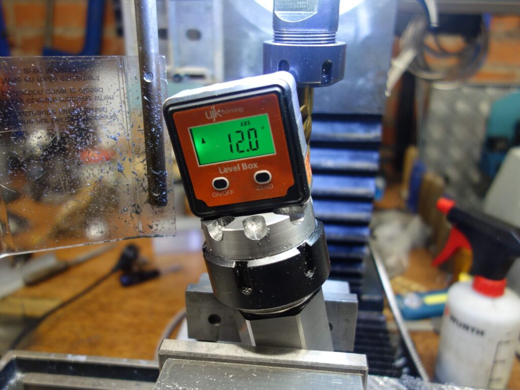
The piece was lastly set at 12 deg to cut a back rake to the cutting edges. This was done by eye with a 14mm end mill in repeated passes until it reached almost to the top of the cutting edge. Of course you must be mindful of the direction of the cutting surfaces when setting up in the mill so the tool will cut clockwise.

Heat Treatment:
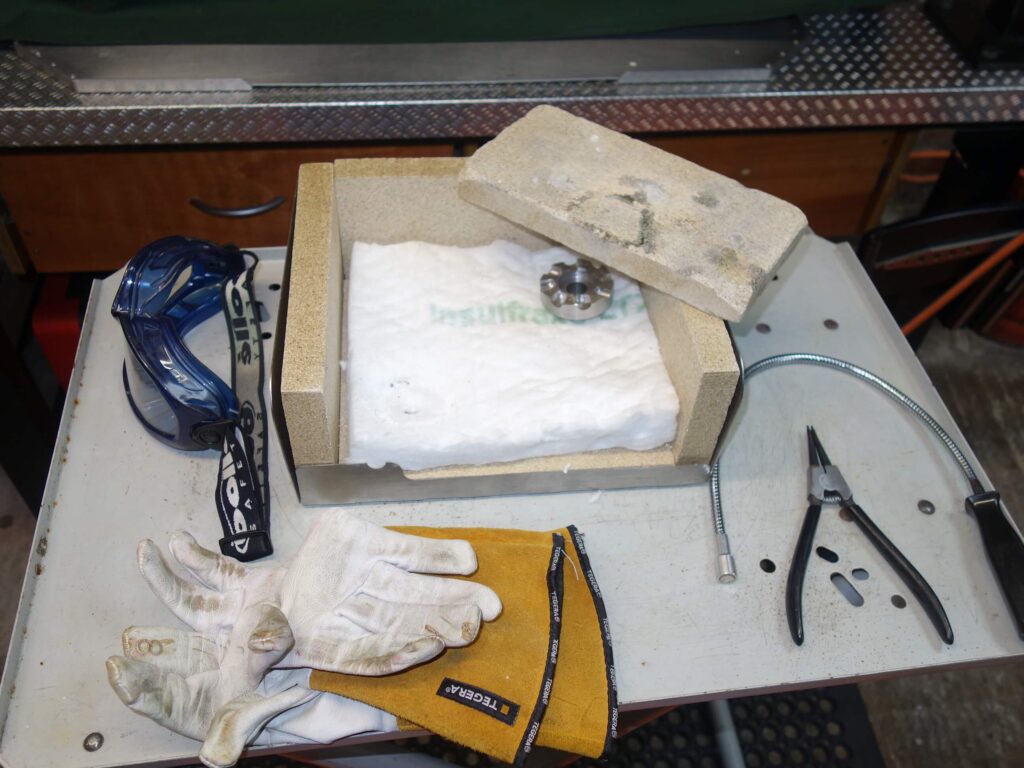
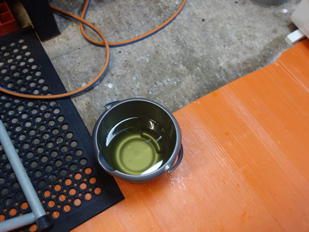
This process is the same as used for the head tube facer and reamers described elsewhere and the T47 thread cutters earlier in this article. It involves using a large torch (I use a size 18 nozzle oxypropane torch) to heat the workpiece SLOWLY to a red heat until it becomes non-magnetic. I held it at the level for 5 minutes or so (opinions vary), then quenched it in Sunflower oil, leaving it to cool completely. The tradition of using Whale oil seems somewhat obsolete. To reduce the hardness it was then tempered for one hour at 200℃, though my halogen oven was probably maxed out at 180℃ on this occasion. The final result, however, seems fine.
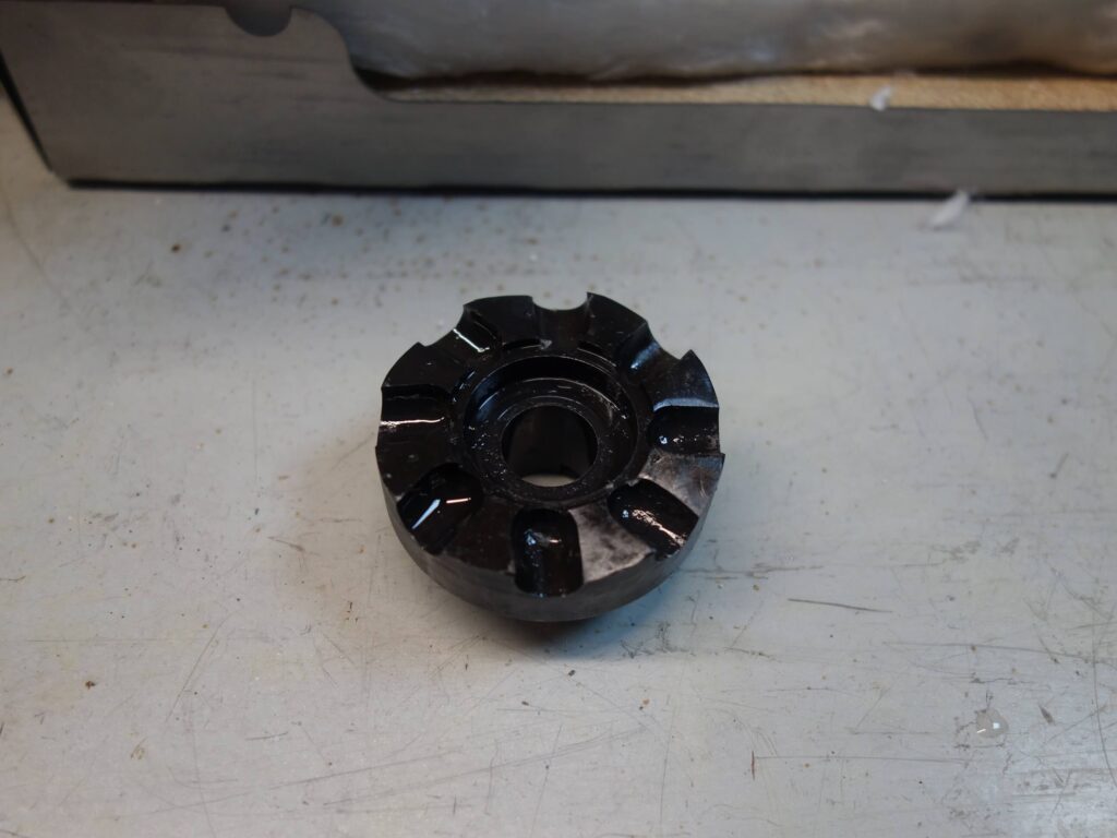
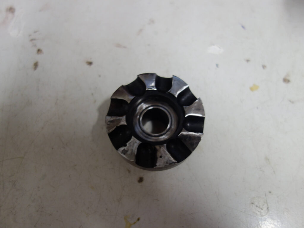

I have yet to try the tool, but am confident it will do the job.
SNH 9/11/25
4 thoughts on “T47 Bottom Brackets and Taps and Facers (UPDATED)”
Thanks Stephen, I always enjoy reading your posts, and am grateful for the time taken to share your discoveries with others. Best wishes, Charlie
Thanks again for the support Charlie
Hi Stephen, I finally have the mountain bike I built last year at the bicycle academy up and running in anger, it has a t47 BB. If you want to have a socially distant (of course) nosey round the bike your more than welcome, seeing as I’m only up the road. drop me an email if your interested.
Thanks Paul,
I certainly will.