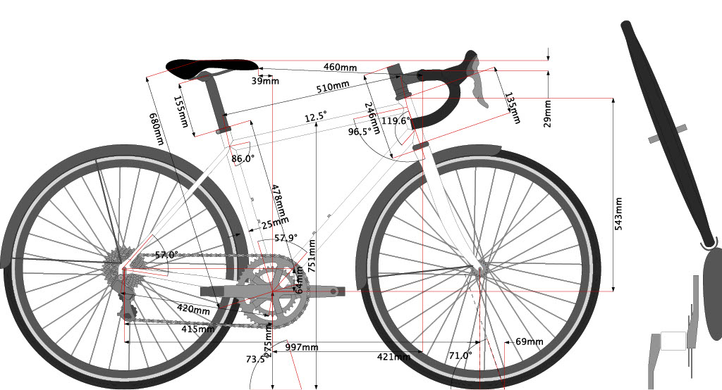
Ladies road bike frames have their own unique problems, mainly because they are often smaller. This means issues with toe overlap, especially if you are fitting full mudguards, but even without, if using 700c wheels. This usually means a potentially shallower head angle and steeper seat angle. You could improve this by using a longer rake fork, say 50mm, but if you want to use carbon fibre these are difficult to find and usually expensive. On this occasion the lady in question was fortunately not very small. The question of ladies geometry is rather irrelevant if you are building a custom frame to a specific person, as the dimensions are going to be governed by the individuals dimensions or their bike fit dimensions.
On this occasion I ended up with a 73.5 seat and 71 head angle, which should give me complete toe clearance for full mudguards, just.
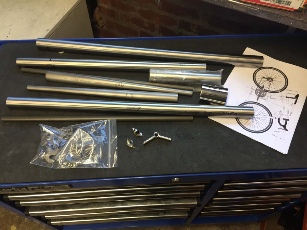
Regarding tube selection for this particular project, well I decided I would use up a selection of tubes I had in and had not been able to use previously, for one reason or another. I also wanted to do full internal cable routing and so to use a T47 bottom bracket I had made earlier, this being the only way I thought I would be able to make a proper job of it. So in the end I used a home made T47 stainless steel bottom bracket, a Reynolds 953 seat tube (31.7 tapering to 28.6 at the top) and chain stays. A Reynolds stainless steel Head Tube (36.4 mm*) and Reynolds 853 Down Tube (34.9 mm). For the top tube I used Columbus Spirit (28.6 mm) and seat stays 14mm Chromo plain gauge tubing. I used 953 plug in stainless rear dropouts plus an aero stainless brake bridge I had in. A stainless steel seat tube collar and cable cover caps. Of course the frame is to be fillet brazed and I will have to use silver because there is not a single joint on the frame which does not include some stainless steel. I will be using some generic winter carbon forks with an alloy steerer and 45 mm rake.
* I usually use head tube rings for a fillet brazed frame to strengthen the insertion of the headset bearings. Please note the Reynolds stainless head tubes are oversize at 36.4 mm, so will not accept the usual 36 mm rings sold by Ceeway. The extra thickness may mean it is adequate without reinforcement, but I decided to make some oversize rings anyway.
Regarding selection of tubes, I decided to use up all the tubes I had in and not used already, for one reason or another. So I have used a Reynolds 953 seat tube, 37.1 at the bottom tapering to 28.6 at the top for a 27.2 seat post. Reynolds 953 chain stays and a Reynolds stainless head tube (36.4 mm*) .The down tube is Reynolds 853, 34.9 and the top tube Columbus spirit, 28.6. The seat stays are cro-moly 14 mm and the rear dropouts 953 stainless plug in. I used a stainless aero brake bridge I had in and stainless seat collar and cable covers. The plan being to mirror polish the stainless dropouts and braze-ons. I also wanted to do full internal cable routing so will use a stainless T47 bottom bracket I made previously, this being the only way I think I can achieve this satisfactorily. As there are no joints that do not involve stainless steel, the frame will have to be brazed with silver rather than brass and will be fillet brazed.
* The Reynolds stainless head tubes are 36.4 as opposed to the usual 36 mm outside diameter. Therefore the head tube rings sold by Ceeway will not fit. As the tube is thicker head tube reinforcements may not be necessary, but I ended up making my own.
A step by step guide to building a bicycle frame
I thought it may be useful to do this build as a step by step guide, albeit A step by step guide rather than a definitive guide. As this is not a basic build I will gloss over the internal cable routing and post something on this separately.
STEP 1 – Cut the first mitres
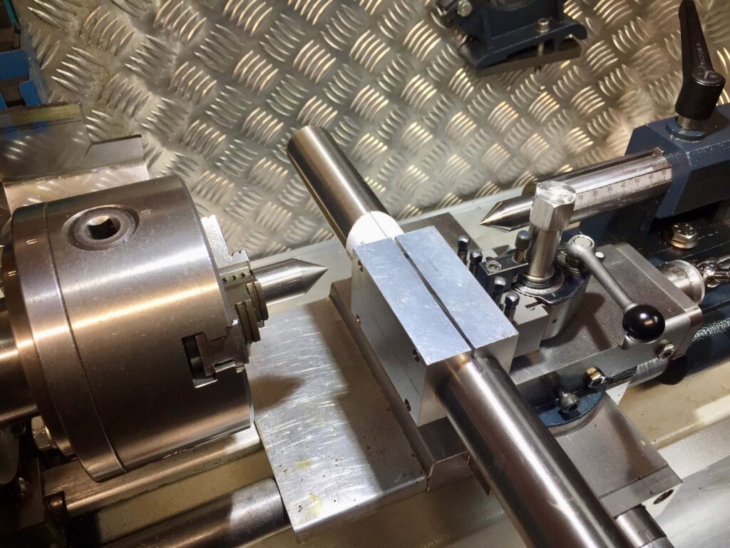
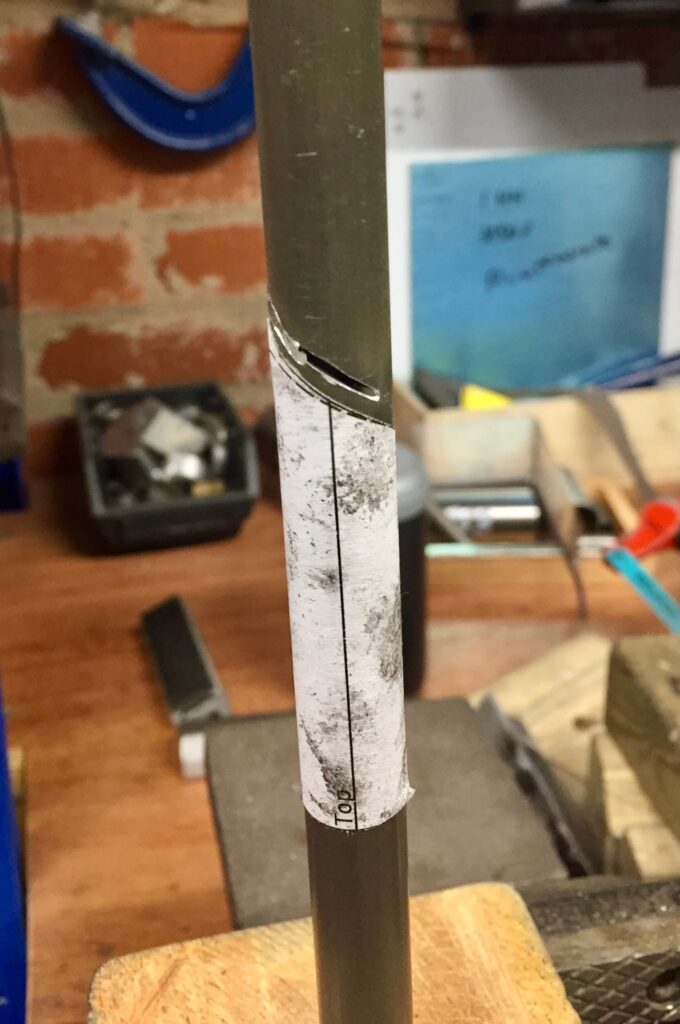
I mostly cut mitres using a lathe or milling machine. Mitering by hand filing is, of course, the traditional method and perfectly fine, sometimes can be even quicker. Using a paper template around the tube makes it very accurate and significantly reduces the skill required. I find machine mitering good for me because it eliminates the tennis elbow, I otherwise develop, during a frame build. I actually use paper templates as well because the hole saws I use in the machines may not be an exact size so it shows up any inaccuracy for finishing by hand. Mostly, however, this is not necessary. The first thing before doing anything else is to draw a centre line down each tube you will be mitering. An ink marker will do, but they rub off quite easily so I now use an acrylic paint pen to mark the lines. You can score with a scribe but I prefer not to do this. Place the centre lines at the front of the seat tube and top of the down tube so you will be able to refer to them for the bottle boss holes in the future. Having drawn the centre line you can then apply the templates at either end accurately and commence cutting the mitres. I do not mitre the top tube and seat stays at this point. Double butted tubing usually has the thicker end sections of different lengths so you need to know which is the short and which the long length. Tubes also come in different lengths so you need to select the tube nearest to the length you will be using. The first miter is usually done at the short end and close to the end. The short end is usually marked on Columbus tubing with a paint mark, and on Reynolds tubing with the product code.
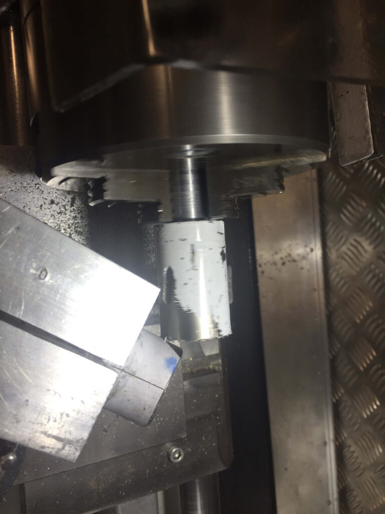
cutting the seat tube notch in the down tube on a lathe 
using a milling machine for chain stays 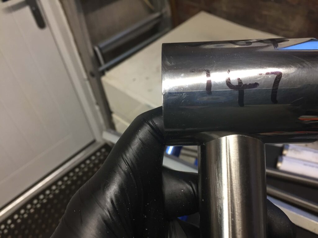
checking the fit of the seat tube on bottom bracket
V blocks are best for holding tubes in machines, and essential for oval stays. The chain stays are cut at an angle to the nearest degree.
STEP 2 – Pre-assemble the frame

Assemble the tubes to check it all fits. Most frame builders use a jig (otherwise known as a fixture) for assembly, but there are many other methods as commercial jigs are expensive, though if you have the wherewithal you can make your own much more cheaply. Alternatively you can assemble the frame, and braze it, in sections. The tubes will need stabilising on a flat surface, such as a surface plate or table and securing in position before tacking the tubes so they can subsequently be brazed fully in a bicycle stand. The possibilities are quite large but most framebuliding schools I am aware of teach frame building using a full frame jig.
You can see from the picture above the rear dropouts have been added and the chain stays can be cut to the right length. Usually most of the length comes off the bottom bracket end so as not to overly widen the tapered end. You have to play with this to make sure the dropout plugs will be a good fit before making any cuts. Dropouts often need slight modification to fit properly. I leave the top tube and seat stays until after brazing up the rest of the frame because there is a chance the dimensions will change slightly so measurements need to be re-checked before the final mitres are cut. You may not wish to do this (see suggestions at the end of the post).
STEP 3 – Pre-polishing any stainless steel items
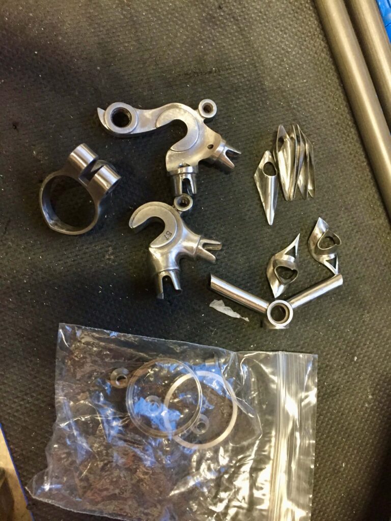
I usually at this stage prepare any stainless steel dropouts and collars etc. that are going to be added. I find this gives me better results when I come to the final polishing after the frame has been assembled because the parts are more accessible to the files and emery cloth. If you are not using stainless steel you do not need to bother, other than to clean and abrade the mating surfaces of any of the parts thoroughly. The same applies to the ends of the tubes that are to be brazed. I clean off the mating surfaces with surgical spirits after rubbing down as it is vital there is no grit or dirt in the brazing surfaces, especially when using silver.
STEP 4 – Vent holes
Vent holes need to be placed in some of the tubes and dropouts because when the frame is heated the expanding air is forced out. This can affect the flow of the filler rod and hence the penetration into the joint. The number and position of the vents will vary, and they can often be hidden, but you need to consider where the air will go when each section is brazed up. A vent at each end of the tube is safest, but I do not always do that. Drilling out bottle boss holes for example will reduce the need to vent the down tube. In this particular build I had to drill a lot of holes in the bottom bracket to accommodate the internal cable routing. Pre-assembling the frame also enables you to mark the outline of the tubes on the bottom bracket and head tube so you can position the vent holes centrally. I would normally drill a vent hole for the seat tube, down tube and both chain stays.
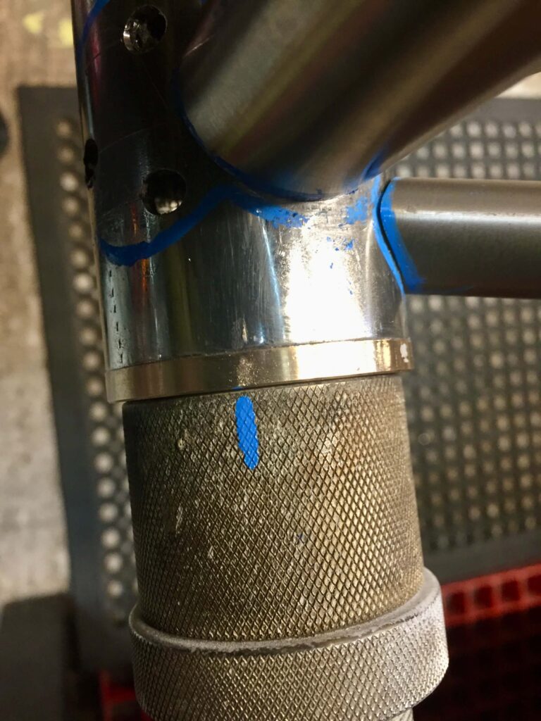
a mark on the jig and bottom bracket aids correct positioning before brazing 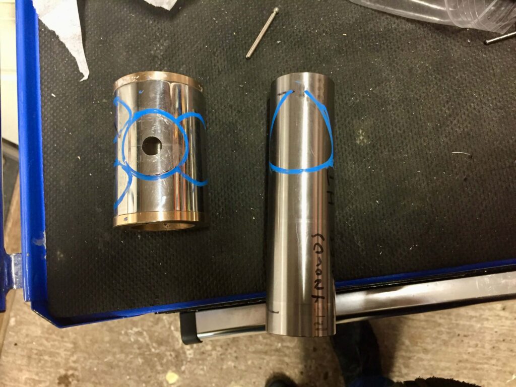

The pictures show bronze bushes screwed into the bottom bracket in this case to adapt the oversize T47 shell to the jig which is only designed for a standard one. They also are to serve as extra protection for the threads so I hopefully will not need a T47 thread chaser after the build is completed.
STEP 5 – Fixing the seat tube
The first step in assembly is to braze the seat tube to the bottom bracket. Some builders would braze most of the frame in one go but I prefer to fix the seat tube first with a narrow ring of braze to make sure it will be fixed and there is no risk of anything moving out of place subsequently. Make sure the bottom bracket is the correct way round i.e. Left hand thread on the right side and right hand thread on the left side.
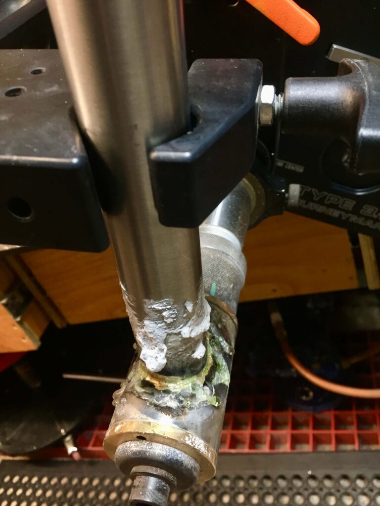
post brazing 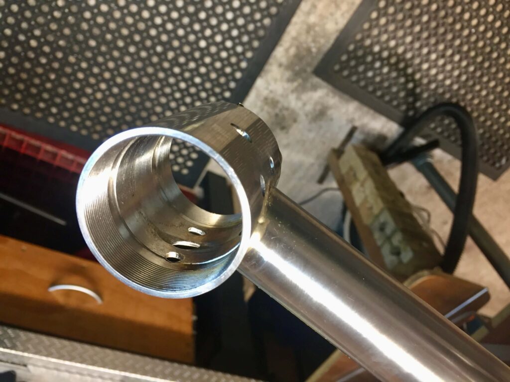
cleaned up showing minimal braze line
At this point I would drill the bottle boss holes in the seat and down tube before further brazing. I re-assemble the loose tubes and line up the bottles, making sure there is clearance above the would be position of a front derailleur. The centre line is used to find the correct position. It is sensible to drill the holes (usually 6mm) before assembly, fixed in a drill press, mill or vice rather than the risky process of doing it in an assembled frame. Start the holes ideally with a spotting or centre drill or failing that at least use a centre punch to locate the drill bit. A wandering drill bit can be a real problem on tubes.
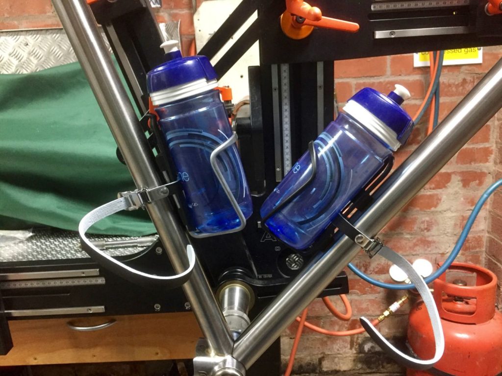
STEP 6 – Brazing the Head Tube, Down tube and Chain stays
You can now re assemble the frame in the jig or your fixture in order to tack together some tubes. Usually I would tack the head tube/down tube first, followed by the down tube/bottom bracket then the chain stays. You can do each of these one at a time, following the tacking process with a full fillet braze, or you can tack all four joints and then fully fillet braze them, finishing the bottom bracket complex all in one go. I tend to do each separately but this is down to personal preference. Some would argue all in one go requires the least re-heating. If you were using a non jig method you would likely be doing the joints one at a time. Tacking involves fixing the tubes in place by melting a small blob of braze into the joint so it is fixed. At least three around the tube is best. You may be able to fully fillet braze the joints in your jig but will need good clearance around the rear of the frame and some ability to rotate and swing the jig as the joints really need to be dependant for effective fillet brazing. It is usually easier to transfer the tacked tubes to a bike stand, such as a Park Tools work stand, in which they can gradually be rotated as you braze around the full fillet.
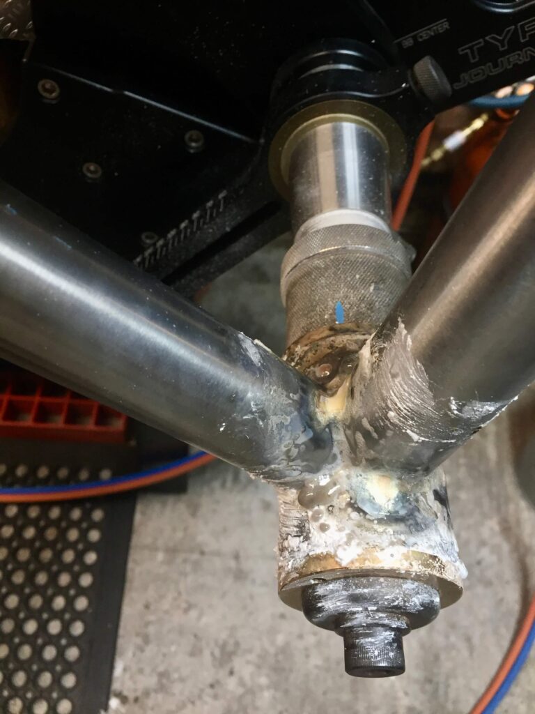
Tacking the bottom bracket to the Down Tube 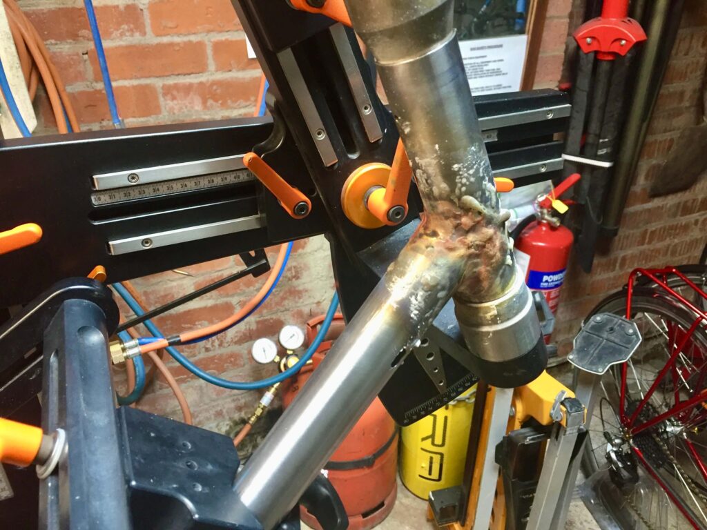
Head Tube actually Brazed in the jig 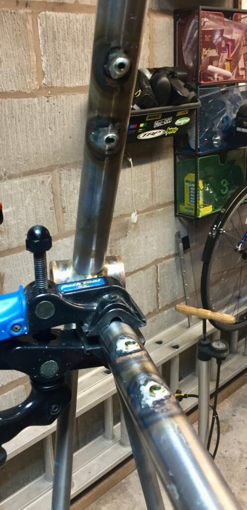
Park stand in use
As you can see I am using paste flux rather than my gas fluxer because I am having to braze with silver as every joint has some stainless steel component. Brazing with silver solder can sometimes be like brazing with soup as it is very runny if you overdo the heat, which can mean expensive drips on the floor.
In fact on this occasion I cleaned up the joints before I brazed in the chain stays and moved on to the top tube first, for no reason in particular.
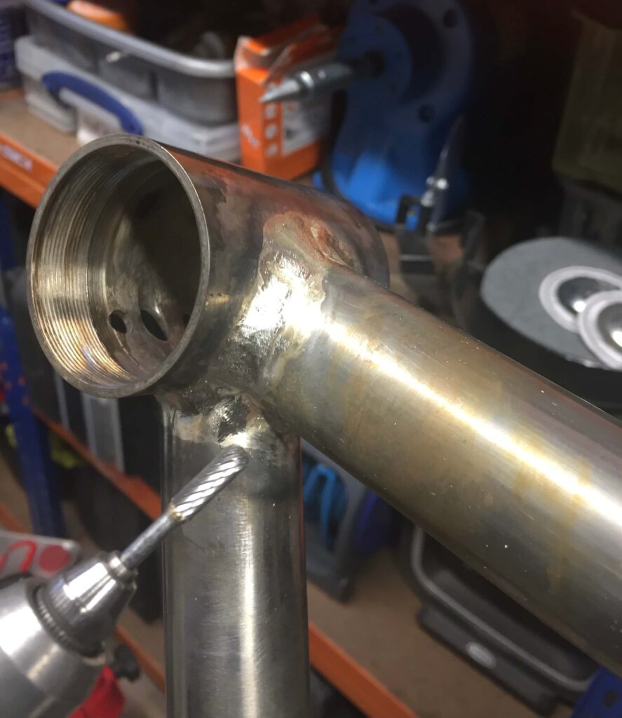
smoothing the joints 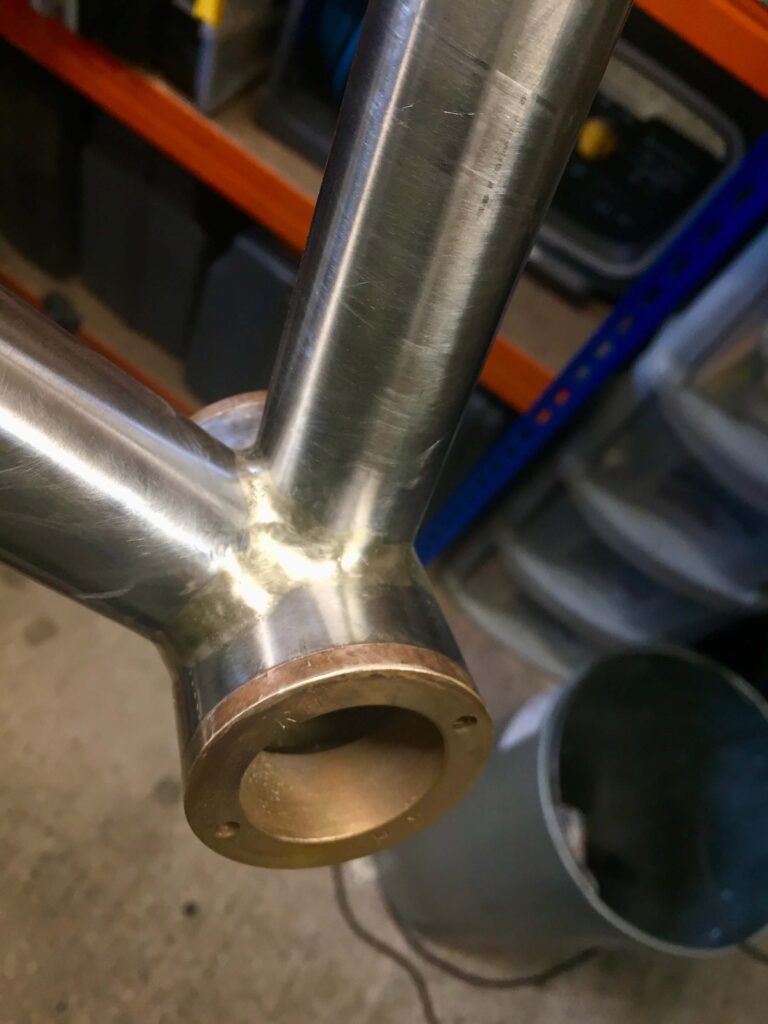
STEP 7 – Adding the Top Tube
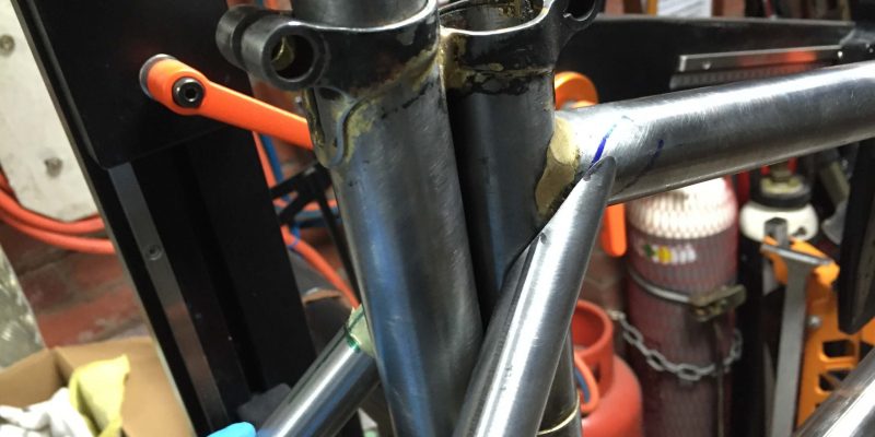
I then miterd the top tube (after drawing a centre line) and ensured it fitted before drilling and fitting the brass tube for internal brake cable routing. This is described elsewhere, or you can simply add braze on brake bosses at a later stage. The tube was held in the correct position in the jig and tacked and then removed to the Park stand for fillet brazing as before. I had already drilled a small hole in the seatpost as a vent to complement the hole previously drilled in the head tube. If you are not using a jig you could clamp the tube in the correct position for tacking.
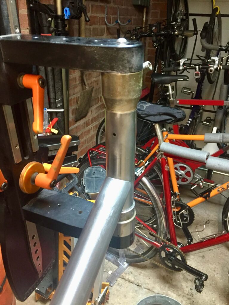
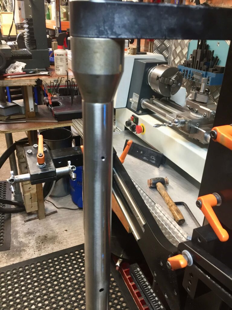
On this occasion I am using a very thin seat tube, and in these circumstances I would recommend using a heat sink, mine being home made. I have not had problems with other non-stainless tubes without it, but I always tend to use it as precaution against distortion now.
When adding templates to the tube be careful, especially with the top tube, to make sure they are the correct way around. It is very easy to mitre one end the wrong way. The centre line is not very visible on this picture but is does demonstrate how the line of reflected light can be used as guide to centrality. This tube also had equal butt lengths at each end.
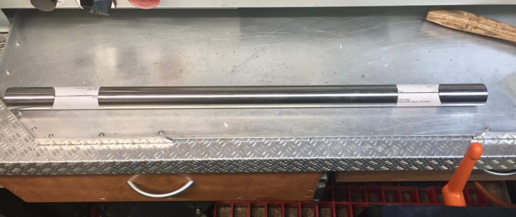
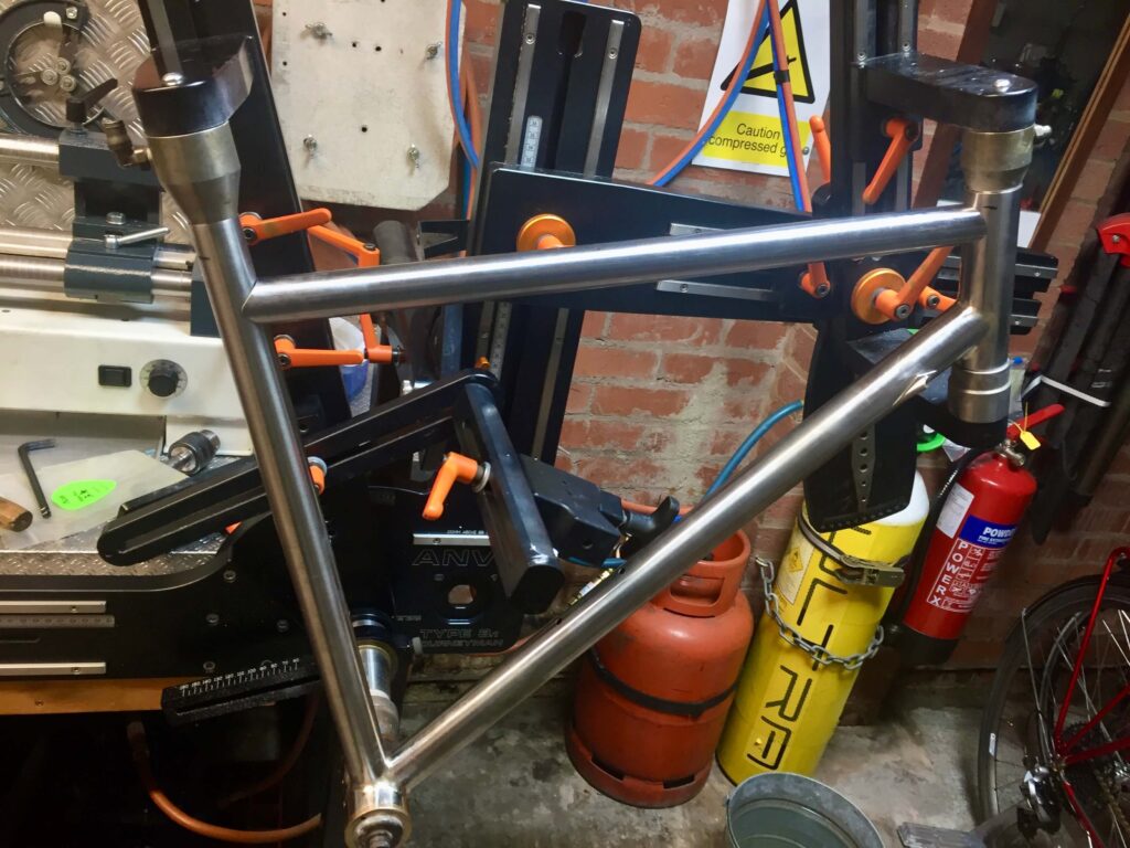
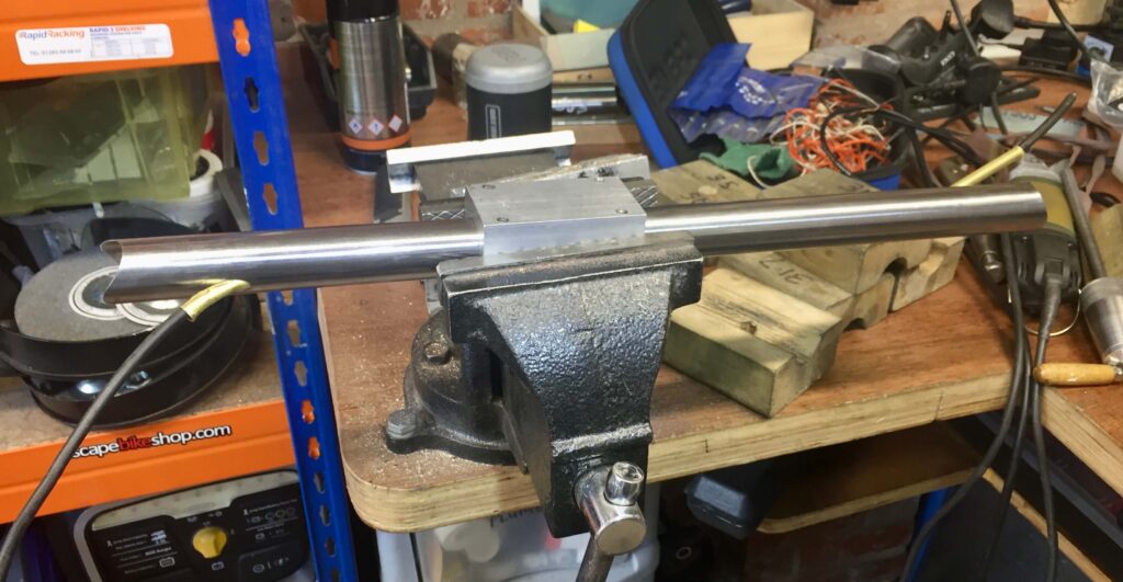
Pulling through the brass tube 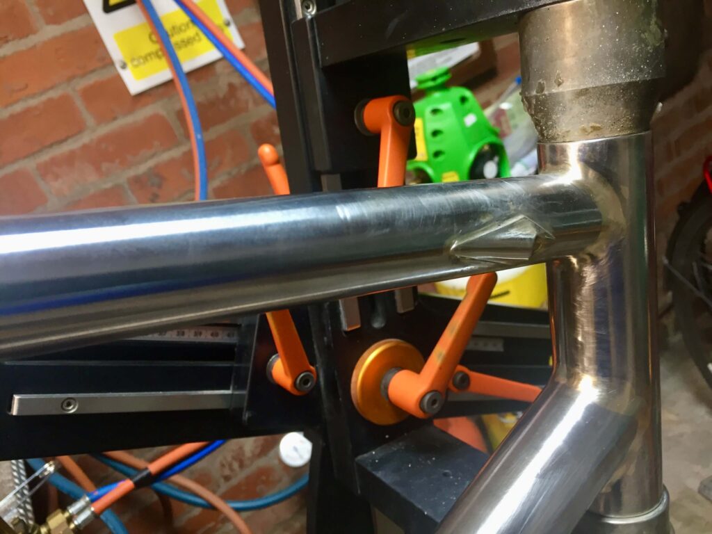
brake cable covers added after top tube brazed in 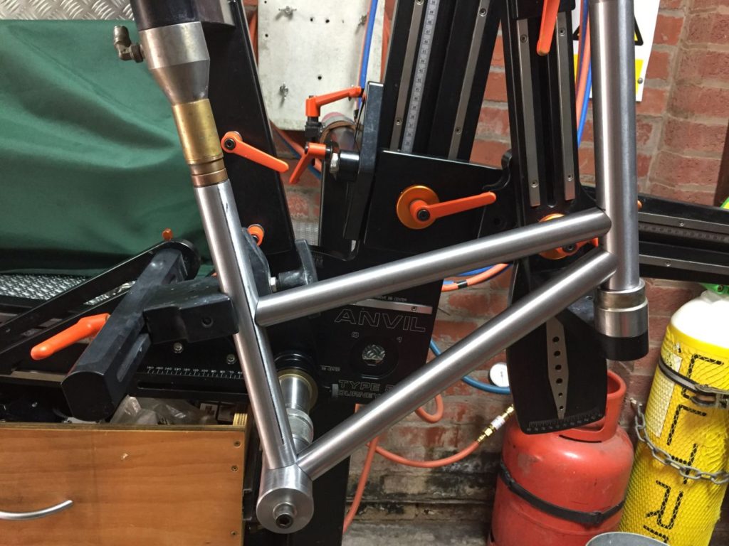
This is a different frame but shows a heat sink in position for demonstration purposes
STEP 8 – Adding the rear dropouts and brazing in the Chain Stays (if not already done at step 6)
I can braze the Chain Stays in the jig OK by rotating it vertically. It also has the ability to tilt from side to side but it is still probably easier to braze in a stand after tacking. Obviously you set up the stays connected to the rear axle at the correct width using the loose fitted rear dropouts. In my experience brazing the chain stays (and the seat stays) always ends in contraction of the rear dropout spacing. My jig was supplied with rear axles oversized by 2 mm, but this does not nearly compensate for the contraction that takes place. The amount of contraction varies and could well be influenced by how accurate you have cut your mitres. You can use a wider axle in the first place and I have used a 137 axle when aiming for 130 spacing, which is the case here.
These particular dropouts are the plug in type, so the neatest way to braze them is to place a coil of brazing rod inside the tip of the chain stay tube with flux then gently push in the dropout. Make sure the rod is of the thinnest diameter available and closely applied to the inside of the tube. This will mean winding it on a rod first of a smaller diameter as it will unravel to some extent. Setting the dropout in a dependant position you can then heat the dropout itself, playing the heat up to the tube and the rod should melt, indicated by it becoming visible at the joint. I even use this process to some extent with socket dropouts.

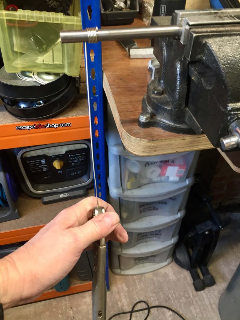
winding the brazing rod 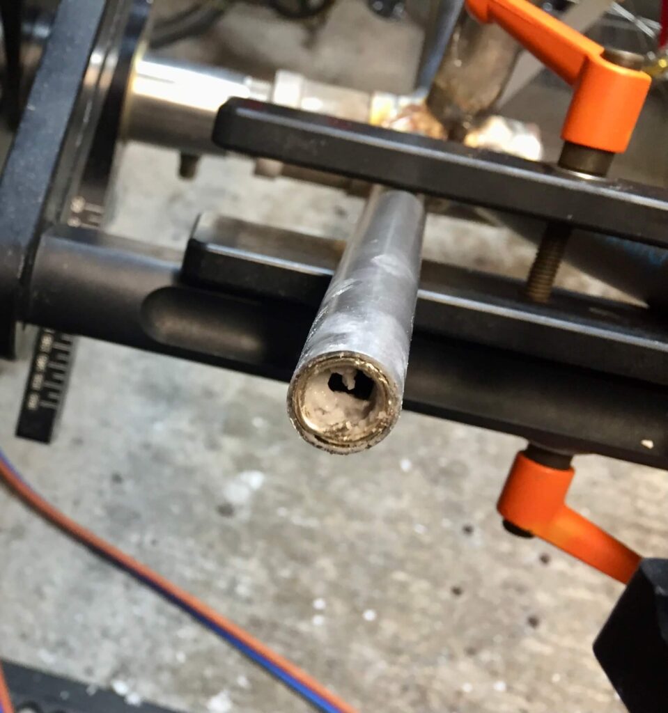
rod loaded 
dropout brazed, also internal cable routing brass tube shown
Following up the brazing of the chain stay dropouts is the inevitable need to widen the contracture of the rear dropout spacing that will likely have taken place. On this occasion the post brazing distance was 126 mm. After securing the bottom bracket in the vice the chain stays are levered open gently to the correct spacing again. Using a dropout alignment tool is a quick way of repeatedly checking they are equal on both sides. If the stay does not break off, you have achieved a solid result!
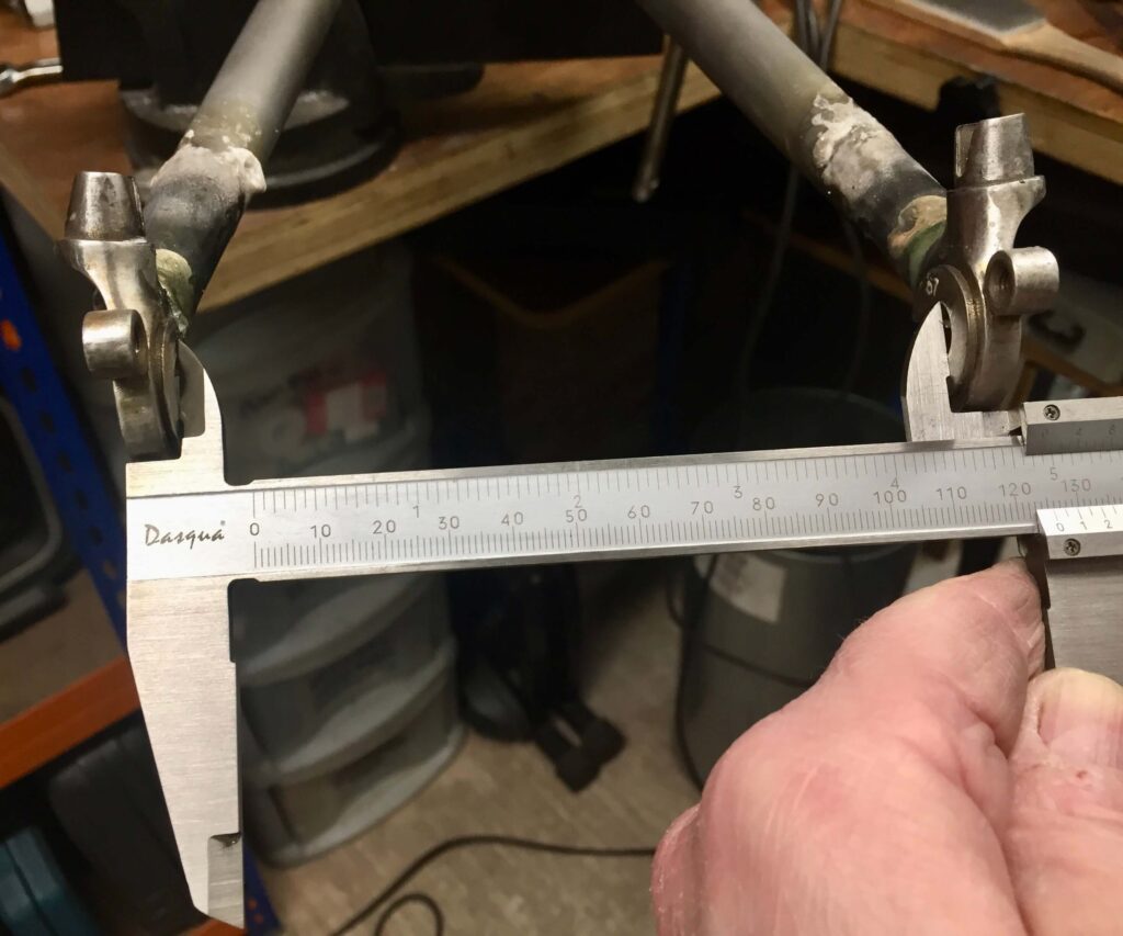
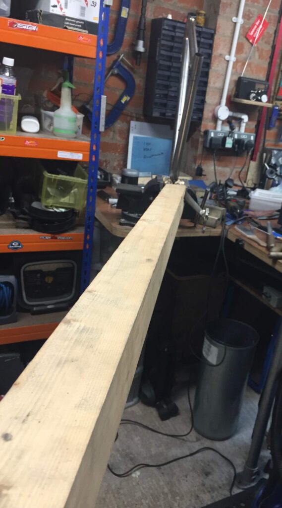
Levering out the chain stays 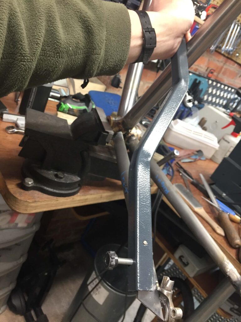
checking they are symmetrical
STEP 9 – Adding the Seat Stays
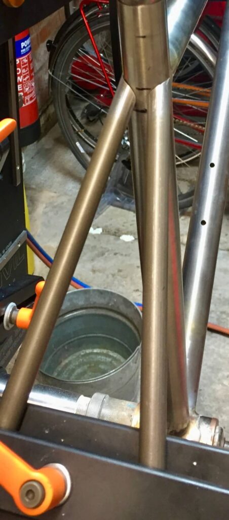
Because you are cutting a mitre at two angles for a seat stay it is usually easier just to do them by hand, guided by a paper template. Of course this is for the blended or ‘fast back’ design. Lots of other methods are used. The down side to this method is it does not give much width so is unsuitable for wider tyres unless you use a curved stay. Cut the mitre first, then when it is right, trim off the length to fit at the dropout end.
cut down with a cutting disc or hacksaw 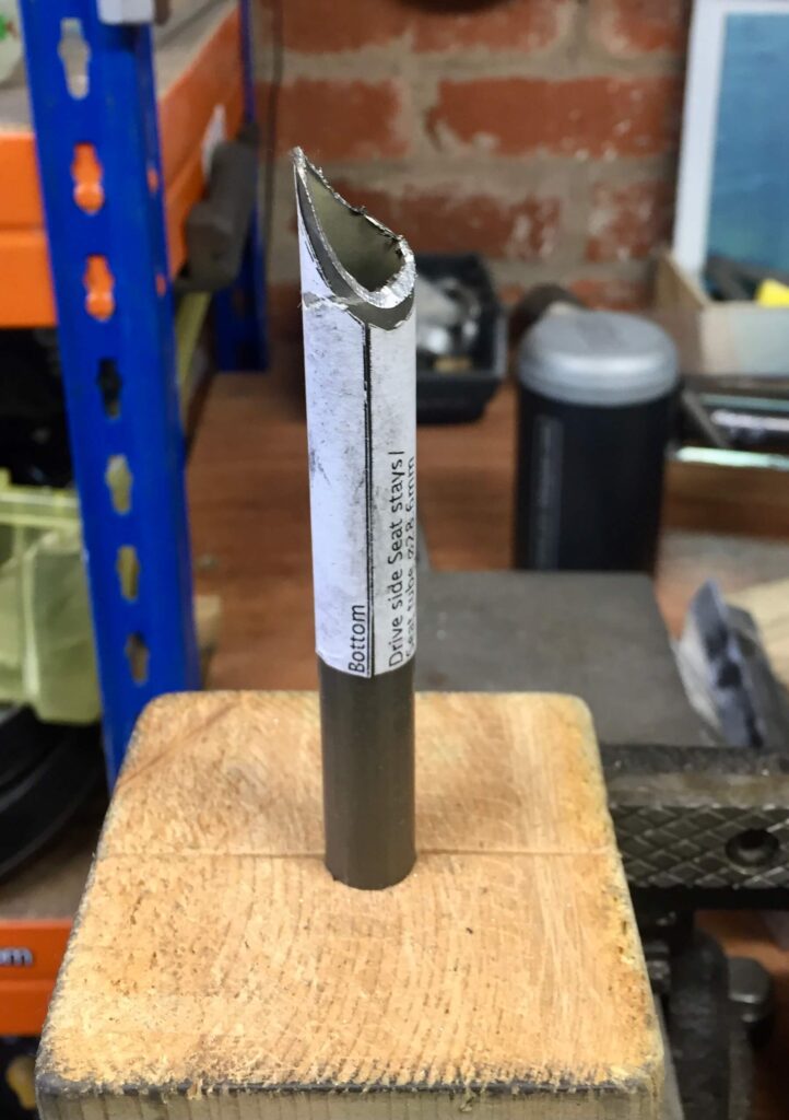
not fully filed down yet
For the seat stay dropout plug I tried using silver solder foil for the first time. This was very successful for the purpose. It is 0.1 mm thick, which is what you need and a piece cut to size can be squeezed in with some flux around the end of the plug and when heated as before will fill the joint effectively. It is probably easier than using a coil of solder but there is less volume, though it is in the right place i.e. around the plug rather than above it.
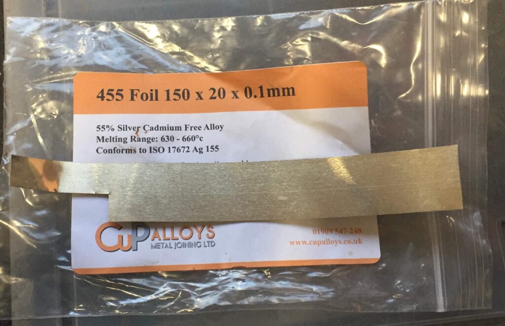
It is likely the dropout spacing will have again contracted so you will need to re-lever out the rear triangle before moving on to the next step. I also clean and smooth down the braze lines again at this stage.
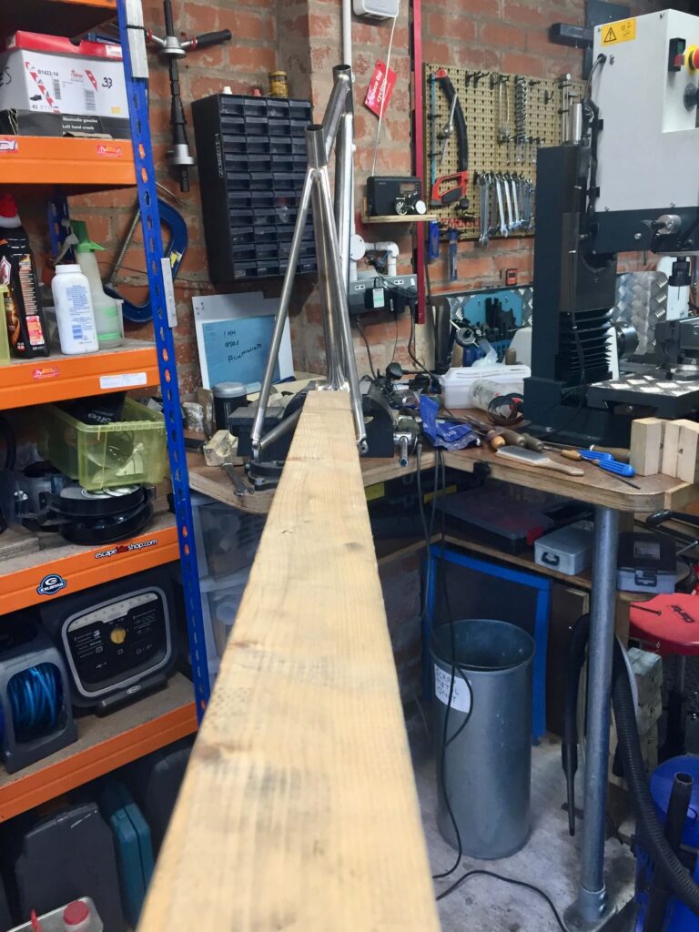
STEP 10 – Adding Brake and Chain Stay Bridges
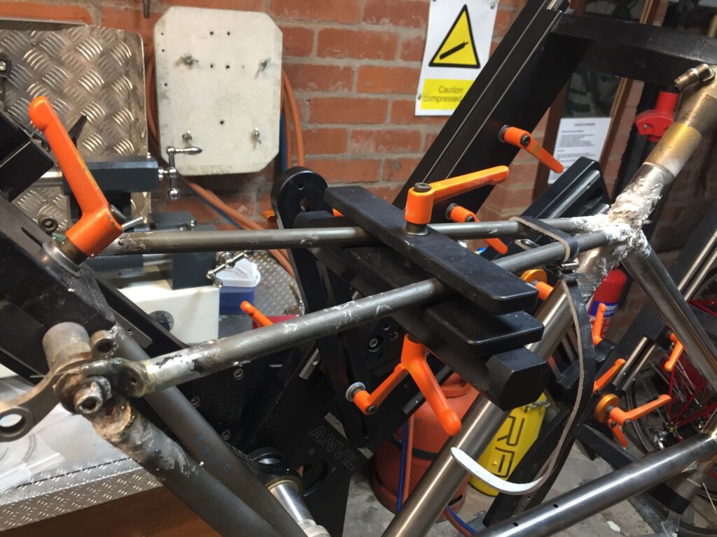
Brake bridges have a habit of moving from where you think you have fixed them, or so it seems to me. This frame needs mudguard clearance, which I always seem to make at a maximum as I hate having my mudguards too close to the tyre. I obsessively check the position and rather than relying on measurement alone, setting up a brake and wheel to make sure I get it right. You can still get creep during brazing and the bridge usually moves up, so avoid setting it too high.
The bridge needs fixing securely for brazing. I have a fixture that clamps the bridge at a variable distance from the rear axle, but it has limitations and as this was a relatively small frame and the seat stays short there was barely enough room to get in to do the brazing, though I managed. I otherwise would have placed clamps underneath the bridge before tacking but some sort of fixture is preferable. I suspect that even if you have tacked the bridge in place it can still move as the tacks melt with the full brazing process due to tension within the seat stays themselves. In fact this brake bridge is held with small lugs so it wasn’t tacked but soldered in by capillary attraction like a normal lug. If you are fillet brazing a tubular bridge, which is more usual, you are best venting it. The brake hole itself can be enough but if this is used for clamping then I would drill a small hole in the inside of the seat stay either side. You have to ensure the seat stays themselves are vented, either through the dropout or through a vent hole in the seat tube at the top. This, however, means the vents are hidden and do not require filling in at a later stage. Some traditional guides mention drilling in the exposed tube and filling at a later stage. If you were to be putting screw in bosses in the seat stays for a rack these would serve as seat stay vents also.
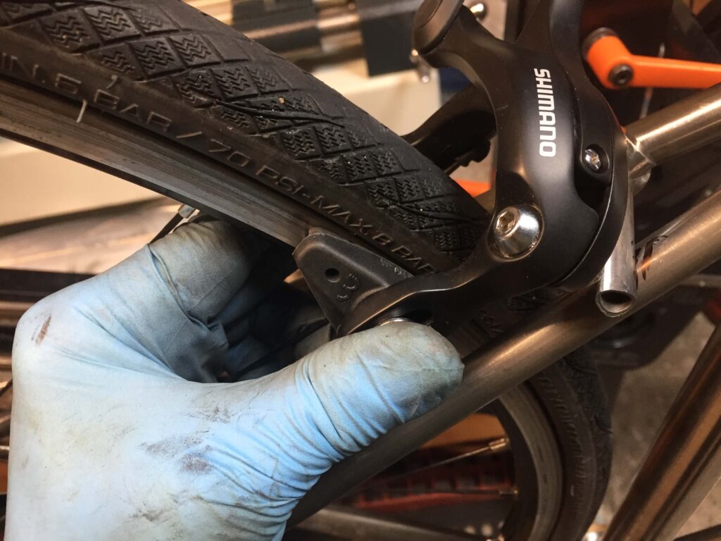
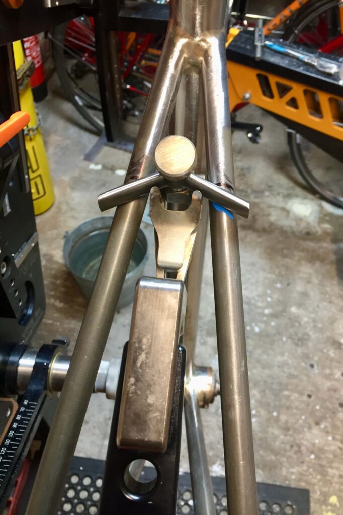
I now mitre the brake bridges in a milling machine which is dead easy using an exact size mill. Just set the bridge at the correct angle and move in to the correct length. Otherwise you have to mitre by hand.
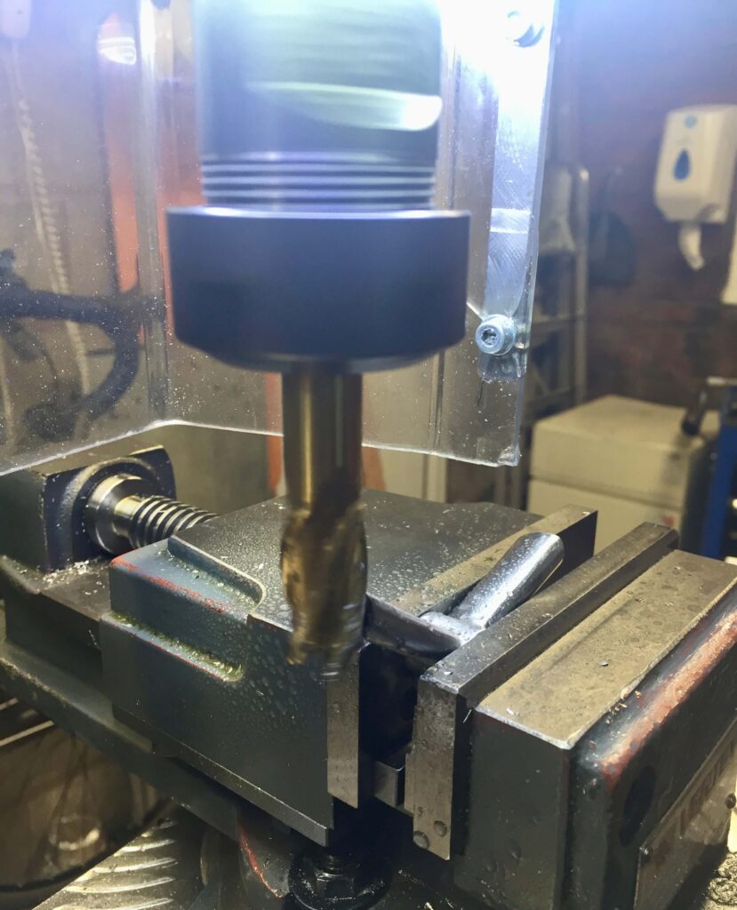
Milling the brake bridge mitres 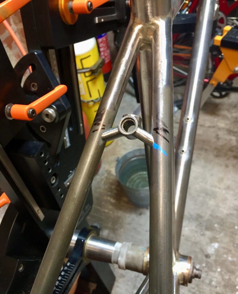
Ready to braze, the fixing lugs slide over the ends 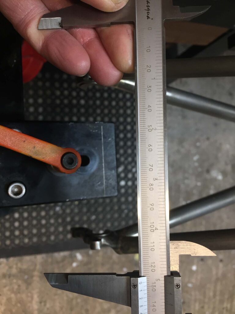
Rear dropout contraction again to 128 mm
I neglected to take further pictures at this point but the chain stay bridge is added in the same manner, often made from a bit of scrap tube. On this occasion I used a cast chain stay bridge I had in, which fitted nicely in the correct position (just short of the distance to the seat stay bridge). It did not require any securing, just gravity. These traditional cast bridges are rarely long enough to fit in the correct position to attach a mudguard and are only usually suitable for race frames where mudguards are not to be fitted. In this type of frame some builders dispense with a bridge altogether. The type of bridge I used is shown below and sold by Ceeway. I drilled a centre hole and tapped it before fitting as I like to fix the lower end of the mudguard with an M5 bolt. If you are using a piece of tube for this purpose you can obviously drill it and braze in a bottle boss.
As usual the rear dropouts had contracted further after brazing in the bridges and needed levering out by a couple of millimetres.
The unused and burnt flux needs cleaning off after each stage. It makes sense to do this rather than leaving it all to the end to check the items have been brazed properly in case anything needs remediating when you come to do the next stage.
STEP 11 – Final braze-ons and hole filling
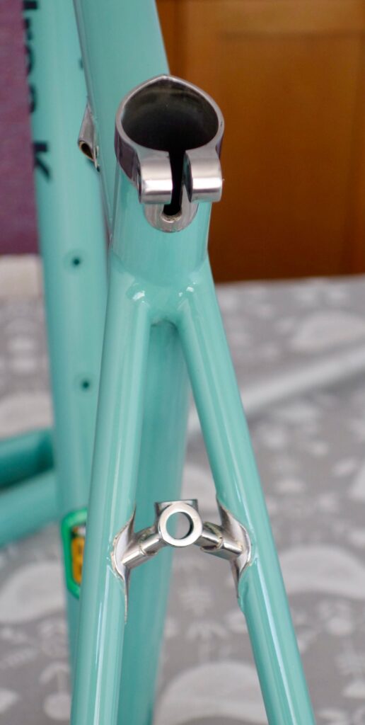
The last brazing procedure is to add the final braze-ons which are usually a seat tube collar, head tube rings, brake cable bosses if using, rear derailleur cable chain stay boss, down tube gear cable bosses if using and threaded bottle bosses. You may also wish to add pannier bosses, and mudguard eyes if your dropouts do not have them. I have often added a braze on front derailleur hanger but this limits you to using a road only front derailleur as mountain derailleurs have different fittings. Sometimes you subsequently make the decision you want mountain gears maybe for touring, so in this case I will use a band on front derailleur hanger for flexibility. The seat collar requires a 4mm stress relief hole drilling and a slot down to it. I find a cutting disc on a Dremmel type tool the easiest way to cut this slot, finished off with small files.
Also go around and fill any exposed vent holes you no longer require with filler rod. In this case there were only the holes in the dropouts. One of the chain stay holes was filled with the internal gear cable tube so I just filled the other one. I left the seat stay holes as they are dependant and can function as drains. You can then go around and check all the joints are smoothed to your satisfaction and the burnt flux cleaned off and a final sand with fine emery cloth to ensure a good clean surface for painting.
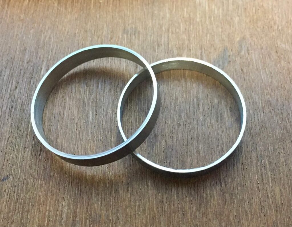
Home made head tube rings 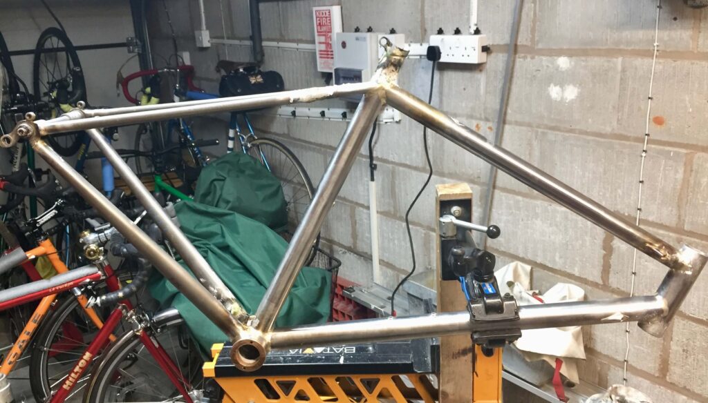
Seat collar and bridge brazing 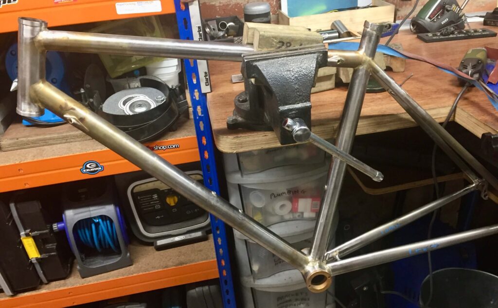
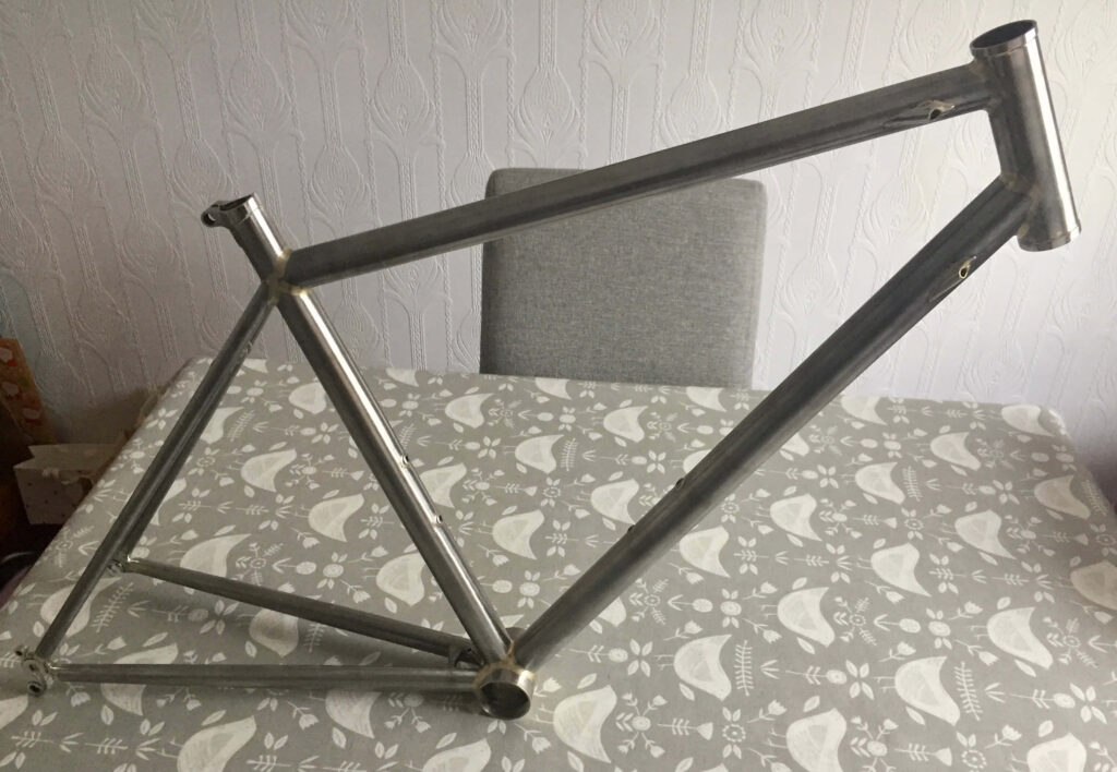
Cleaned up frame 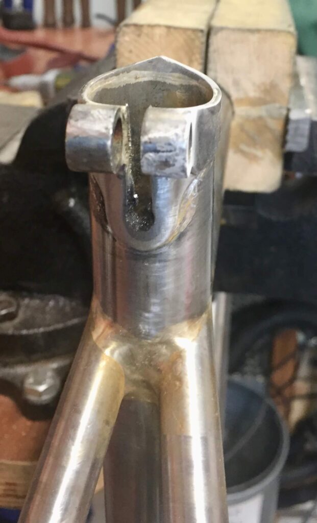
Cleaned up and cut seat collar
STEP 12 – Tapping, Reaming, Facing, Stamping and Final Polishing
The very last stage is to clean out all the threads on the frame by re-tapping them. This includes the bottle bosses, gear bosses and bottom bracket. Integrated steel derailleur hangers are usually OK but note these are usually a metric 10 mm x 1mm thread. Standard 10mm taps in sets are usually 10 x 1.5 mm so you have to make sure you source the correct tap for this. On this frame I went to great lengths to preserve the threads in the T47 bottom bracket, as I do not posses the very expensive T47 taps. Using screw in bronze bushes and a bottom bracket heat sink worked very well to achieve this.
Usually I would chase out the bottom bracket with a tap, however, and also face the bottom bracket at the same time. Facing cutters should be used to take off the minimum to make sure the bottom bracket is square as they can quickly remove quite a bit of width. Whilst ideally bottom brackets should be made a little wider to compensate for this, they rarely are.
You also need to ream out the seat tube to the correct size as some distortion is inevitable during brazing. I have always use an adjustable hand reamer with no issues, but fixed size reamers are available at a price. Use plenty of cutting oil and rotate clockwise only on insertion and removal to prevent blunting. Use an existing seat post to check for fit as you go. It needs to slide in easily.
The head tube also needs facing and reaming out to your headset size. The tool for this usually does this in one operation albeit one end at a time. Again turn in a clockwise direction only.
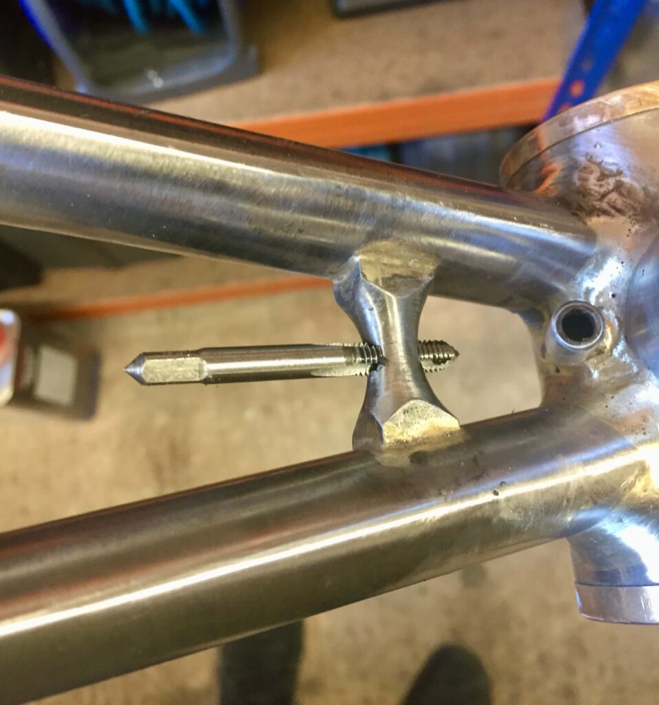
Cleaning out the thread in the chain stay bridge 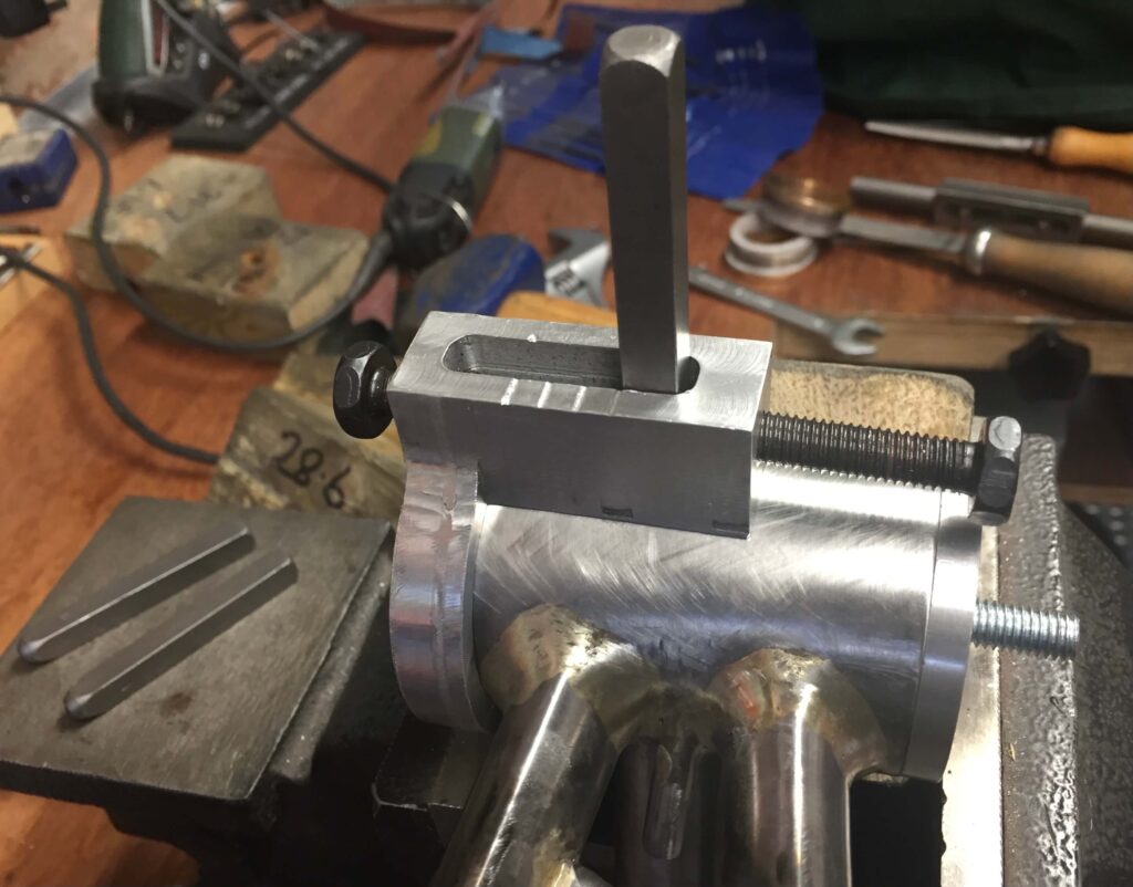
Traditional stamping of the bottom bracket
Very last thing is to polish up any stainless steel fittings you wish to have a mirror finish. In this case the seat collar, head tube rings, brake bridge, internal cable covers and rear dropouts. As they were polished up beforehand this should be a lot easier but still requiring possibly some filing and further sequential sanding with emery strips before the use of graded buffers as described elsewhere.
Some further thoughts on assembly
The order of assembly I describe is just my way, and even that changes. You could mitre the entire frame and tack every joint, followed by brazing all the frame tubes in one go. This is something I would consider if I were brass brazing using a gas fluxer. However if using paste flux, as here, I think fluxing up an entire frame and brazing in one go would be rather messy, which is why I did not contemplate doing it, though in the final analysis it probably would be a lot quicker.
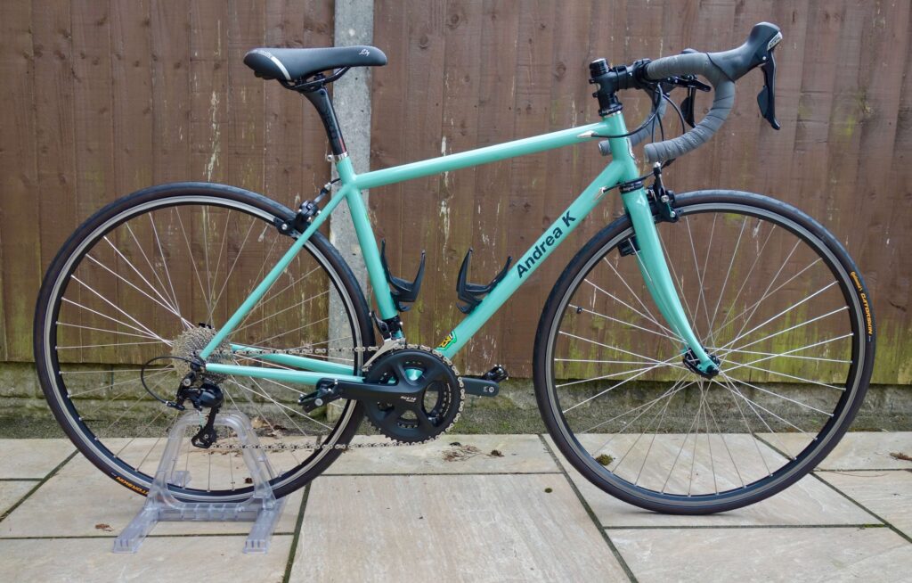
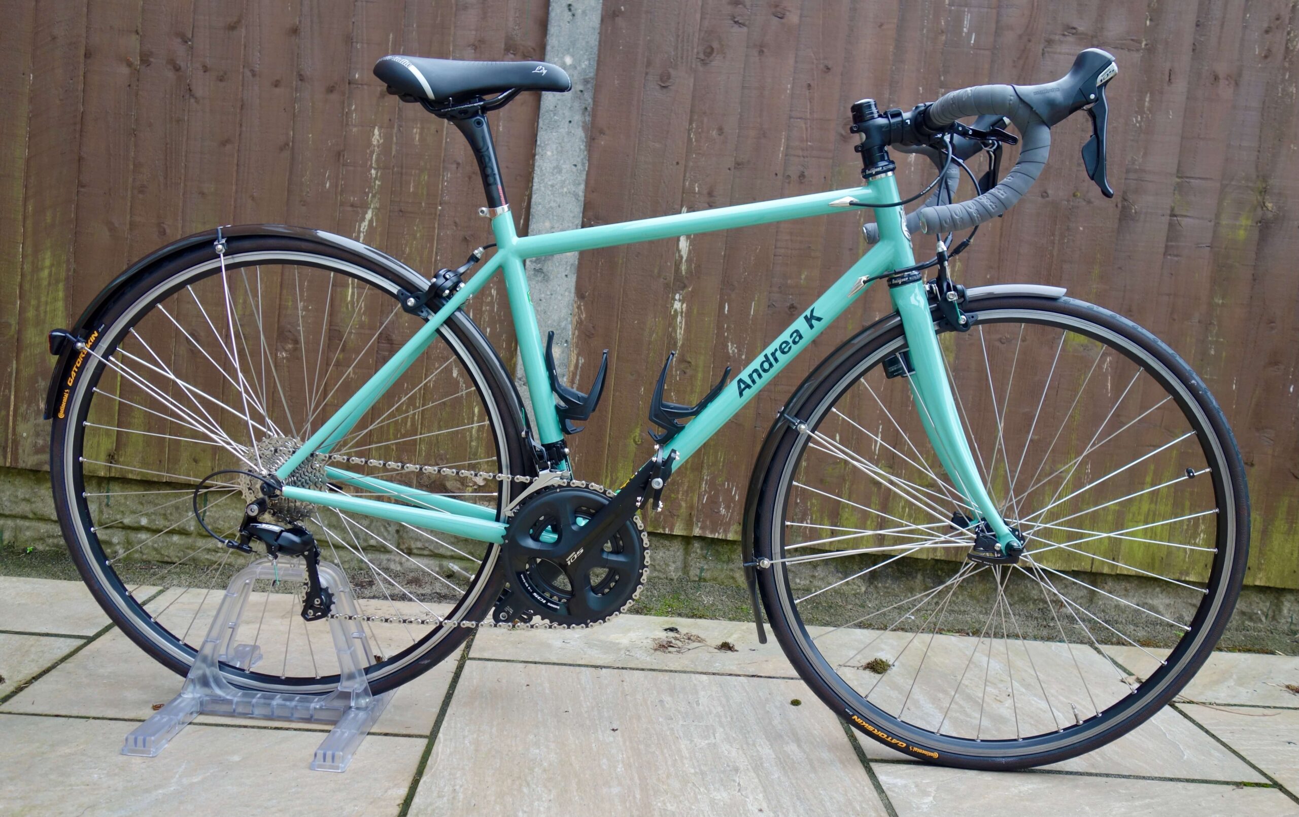
The Finished Article