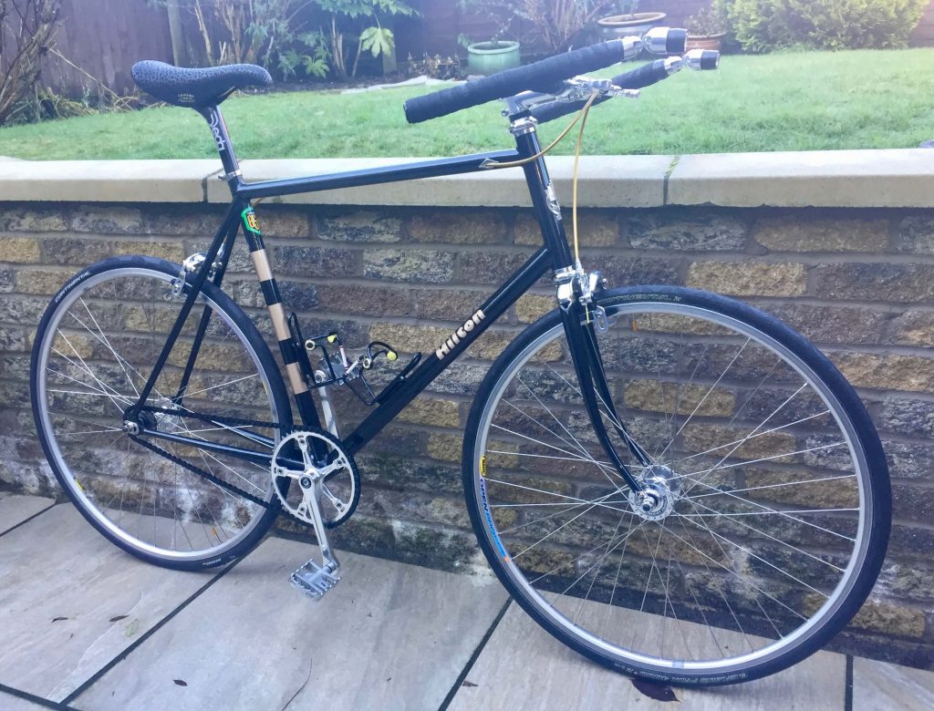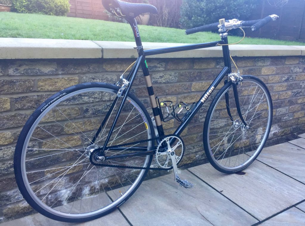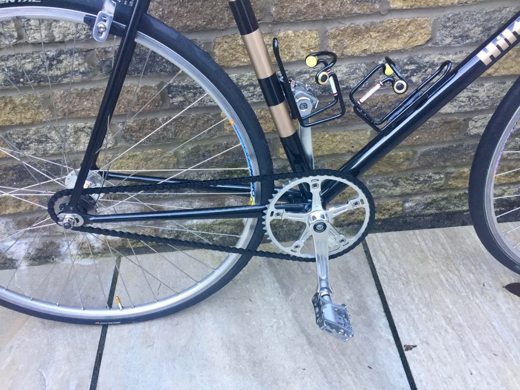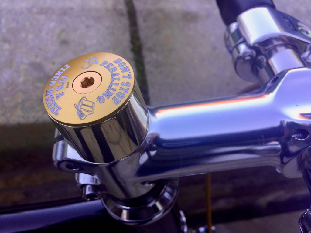
I had my 1969 Bob Jackson Merlin frame re-instated to an original specification, which left me without a fixed wheel bike.
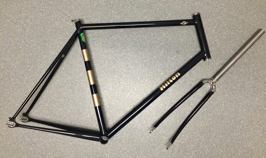
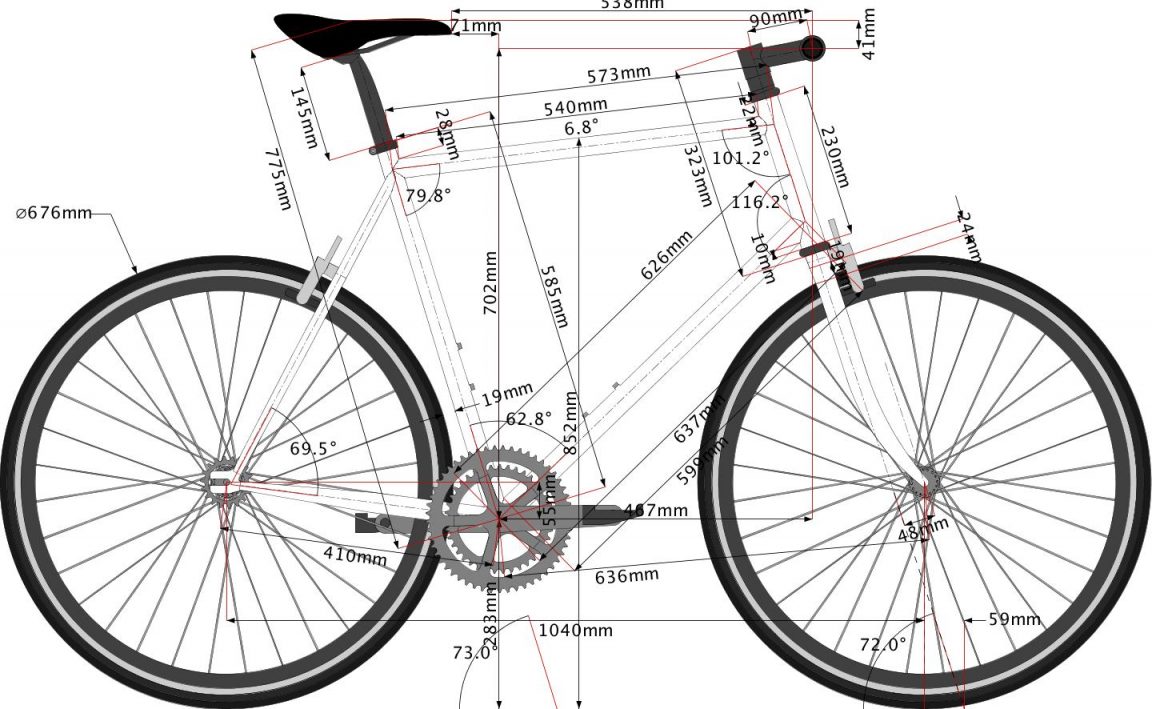
I decided therefore to make a track specified frame suitable for the road with brakes but otherwise lacking protrusions so it would in theory be able to be used legally on a track with a bit of stripping down and change of wheels, not that it is likely to be used for that purpose. It also would have a higher bottom bracket for track use, which is a good idea for fixies anyway, reducing the risk of striking the pedals on the road when cornering. I did however choose a more conventional road geometry for the frame. As usual I also used it as a test bed for some more customised parts and for my new custom handlebars.
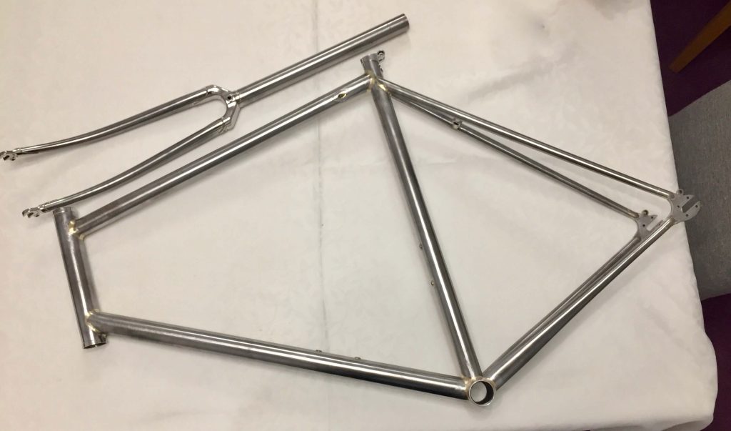
The frame is made from oversized 853, with 853 fork blades but a Columbus Head tube and seat stays, this being pretty much what I had in. I decided to use up the seat tube I had in, tapered at the top to a 27.2 i.d., despite having vowed not to use these again. I had to be especially careful to take all the length reduction of the bottom of the tube to retain as much of the 27.2 diameter at the top as possible as I have always thought these too short for securing a seat post. The frame is also fillet brazed apart from the fork crown.
I intended to use standard track dropouts but only the flat plate type were available to fit the design and tubing. I have always disliked the idea of slotting tubes to accommodate dropouts then sculpting the ends with filler braze so I decided to experiment with jointing pieces to connect the tubes to dropouts. These have been sold by Paragon Machineworks in the USA, described as ‘Bullets’, but in rather large diameters. My version is probably somewhat heavier duty.
The final touches were to use an internally routed rear brake cable and make some flat covers, together with integrated mudguard mounts.
The Forks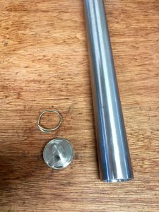
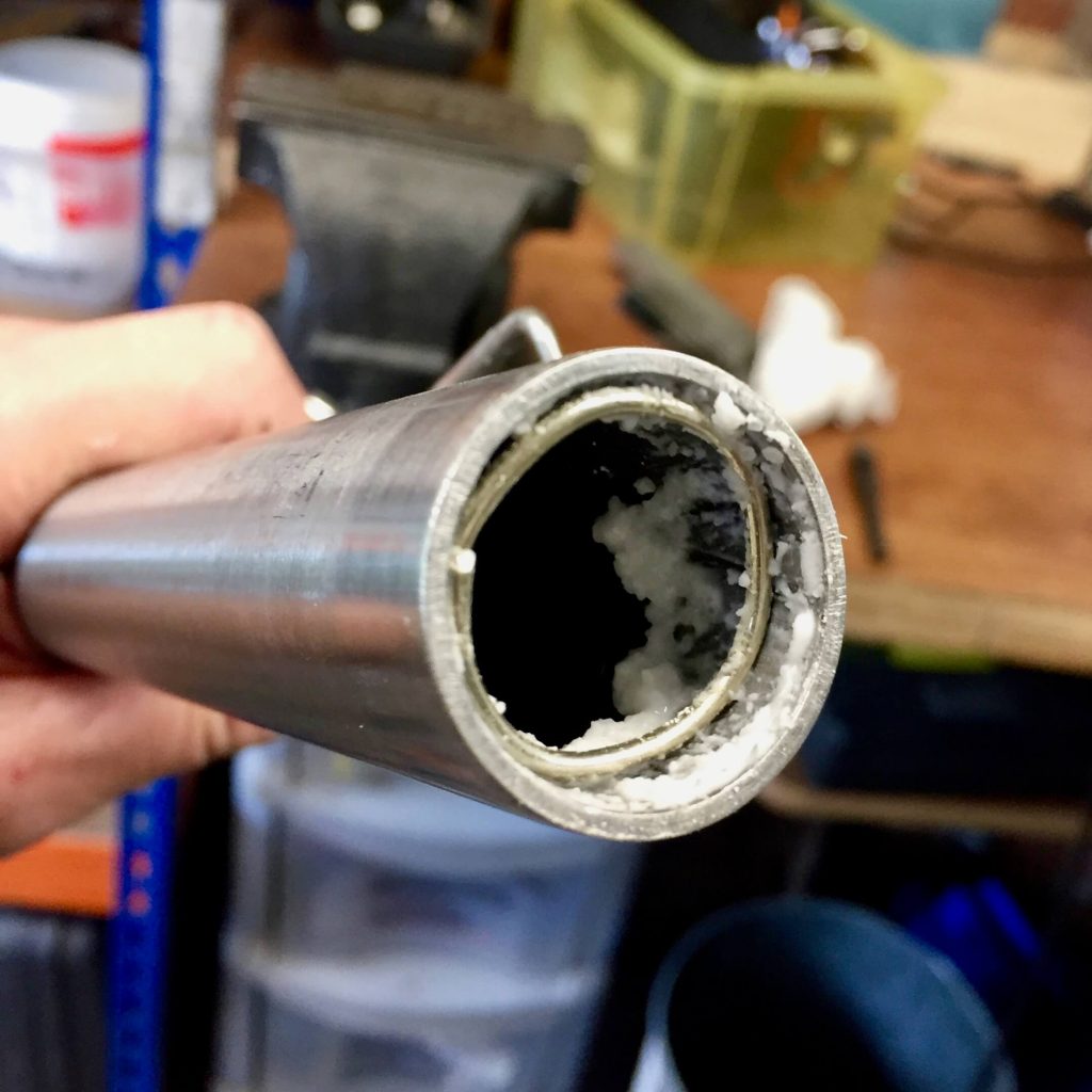
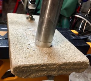
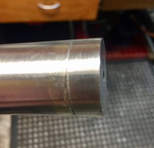
I planned to make a better job of the mudguard mount than I had in the previous project so used the lathe to make a one piece, tapped M5, stainless end cap. This was then brazed into the end of the (non stainless) steerer tube with sif No2 brass rod. The picture shows the ring of brass rod inserted into the end and heated up clamped on a non-conducting Vermiculite block. This is generally a BAD IDEA, especially with brass and oxy-propane, as it needs a lot of heat and I only just got away with it. Silver is easier but I wanted this end cap to remain in place when I silver brazed in the fork crown. It is very difficult to bend even a thin brass rod to make good enough contact with the metal tubes to receive the applied heat, more of this later. The next step is to fit the dropouts to the fork ends as they rarely fit exactly. I thought I had hit on a simple way to bore them out to fit on a lathe, as in this case they were a little tight.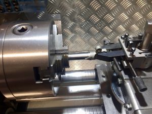
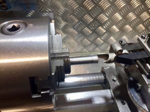
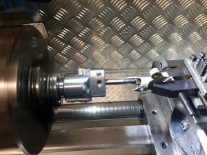
The idea is to turn a plug to the existing diameter of the dropouts, then put this in the lathe chuck so it is central. Then mount the dropout in a toolmakers clamp which will then clamp in the tool post of your lathe. Retract the dropout when it is fixed in position and put a small boring bar in the chuck. This then enables you to bore out the dropout gradually to give a good test fit of the fork blade.
DO NOT WASTE YOUR TIME! This is a clear case of over thinking the task. After about an hour of playing with this I gave up and went back to using a carbide burr on a Dremel, which takes about 5 minutes!
After setting up the whole fork in the fork jig I brazed the stainless fork crown and dropouts with silver.
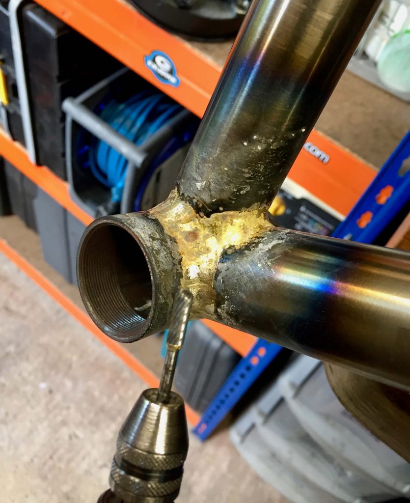
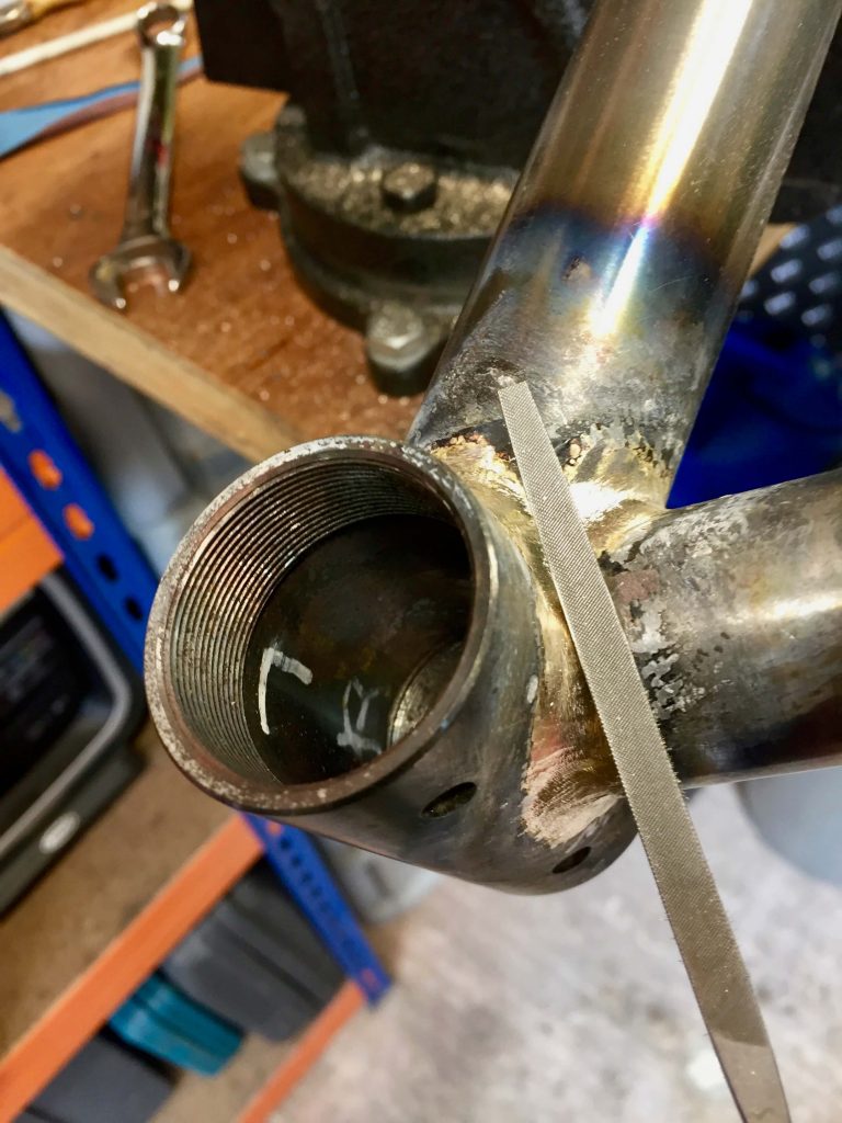
the protrusion out of the fork crown could be filed down but using a milling cutter and carbide burr speeds up the process.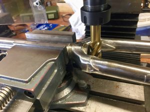
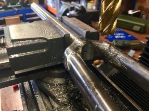
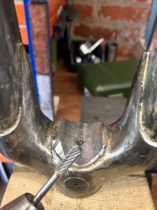
All that remains is the final filing and polishing of the crown and dropouts, which had been pre-polished before assembly.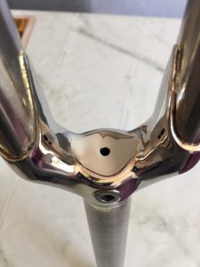
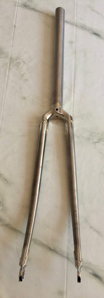
The Frame
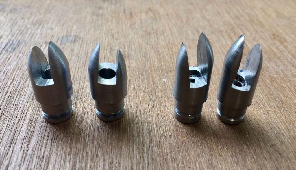
The first task was to make the connecting pieces for the rear dropouts. I made these from EN8 medium carbon steel. I chose this because it is easily available and the material specification seems OK for the purpose. The rear dropouts are not stainless but have bolt on stainless faces. The connectors were turned on the lathe and the ends completed with a ball turner to make them round and the slots were done on the mill at an angle of 7 degrees. I put a groove in the shafts to accommodate some brazing rod. The ones on the right are for the seat stays and simply push over the existing tabs on the dropouts which I felt would be adequate. The chain stay tabs on the dropouts were, however, modified by filing them round to slot into the large holes in the connectors for a more rigid result.
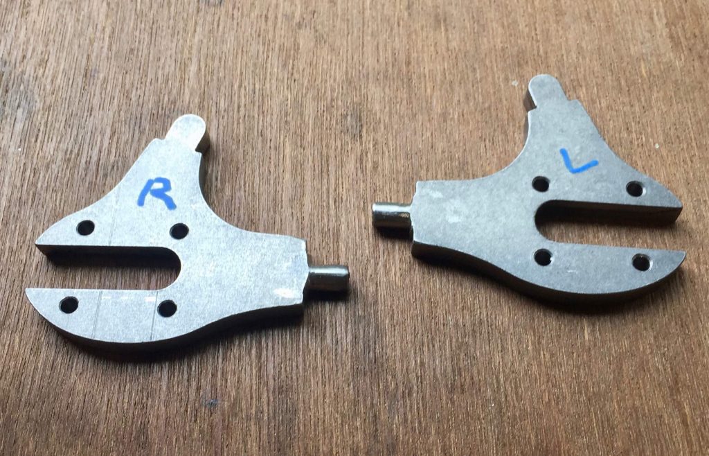
The chain stay connectors were then brazed to the dropouts using sif 101 brass rod, mainly introduced through the centre hole. The subsequent brazing of the rest of the dropouts was done with silver in one go.
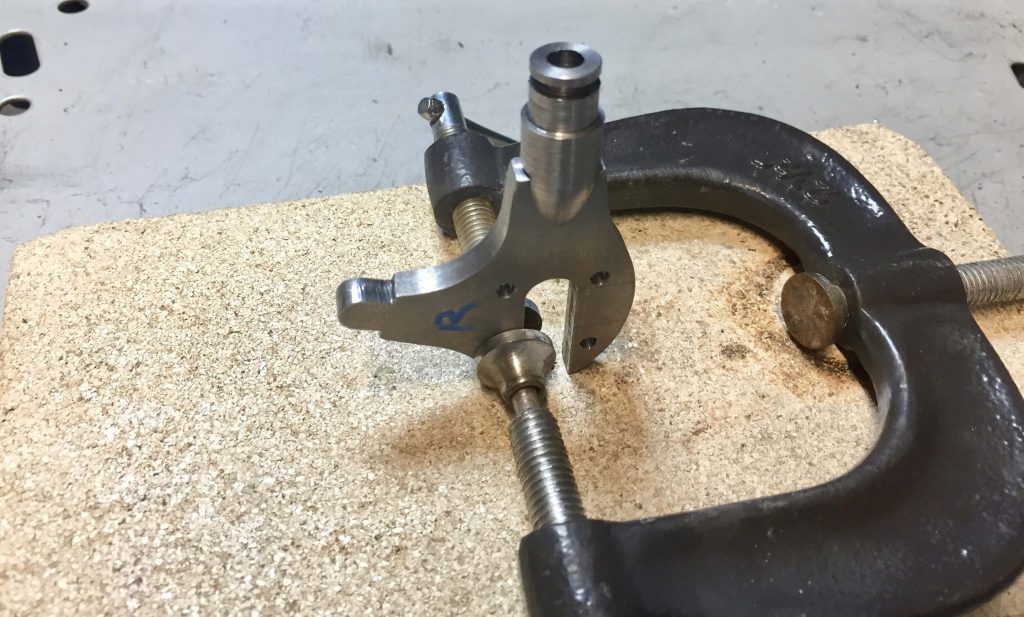
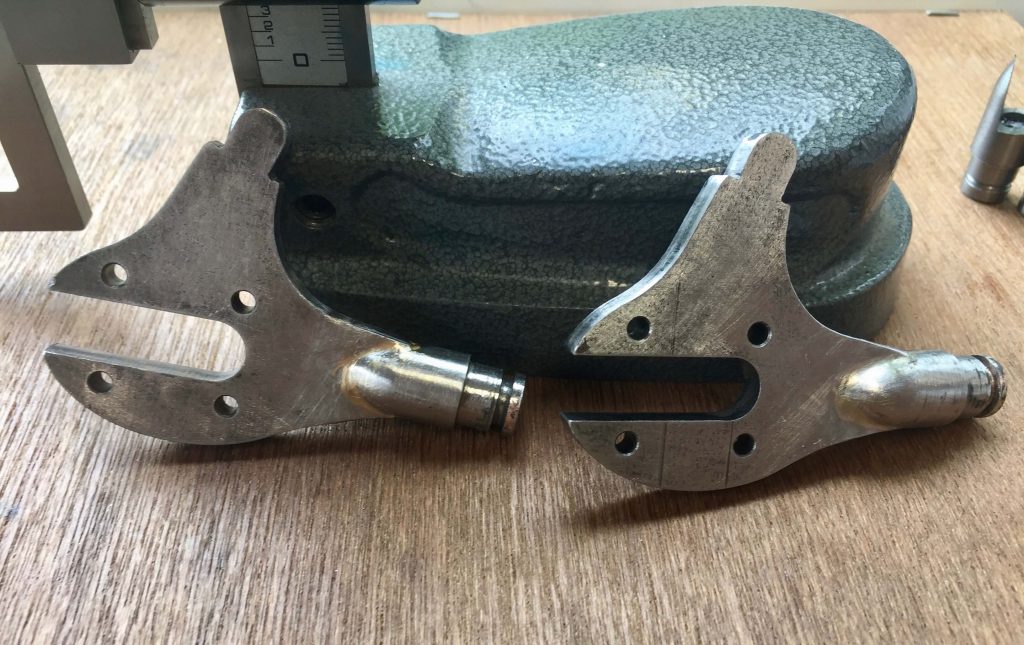
I then did something I usually never get around to, that is cut and mitre the whole frame before assembly. I usually cannot resist starting on the main triangle and sorting the rear triangle later, but I am sure it is best practice to prepare the lot first. The order of the actual brazing is a matter of personal preference if you ask me. I invariably start with brazing the seat tube to the bottom bracket which gives the best fixed reference point. Make sure you fit the bottom bracket the correct way round, then drill your vent holes for the adjacent tubes.
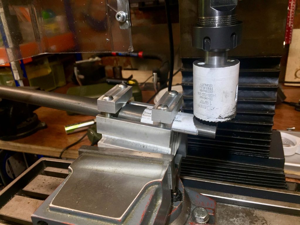
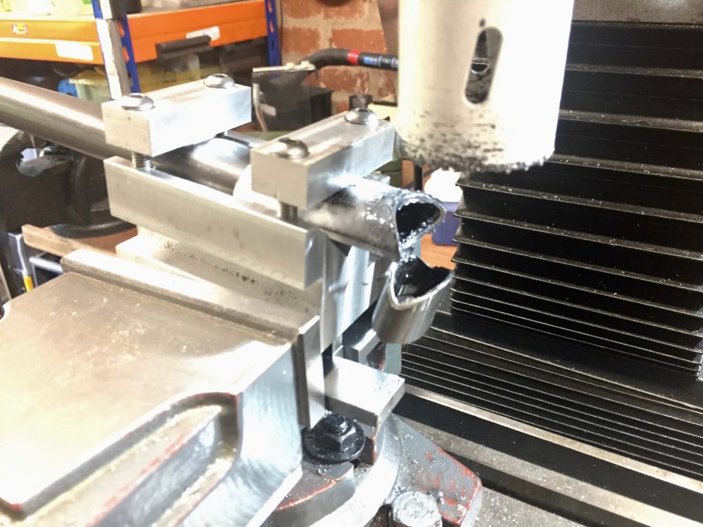
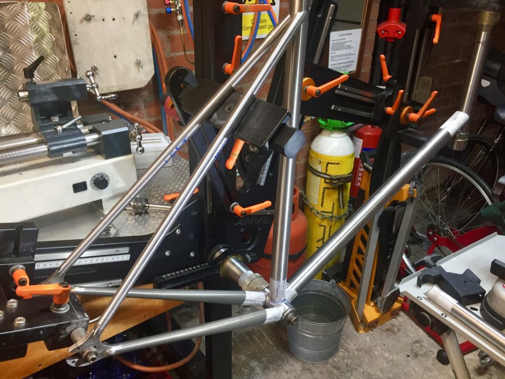
I am now mostly mitering using a lathe but the top two photographs show that using the mill is much easier for chain-stays due to them not being round. Mounting in a V block makes it easy to set them square to the hole saw and the whole block can be angled. I do not have a angle vice, so the V block sits on 7 degrees of angle block. I feel setting the mitre angle to the nearest degree seems to be enough. If you are mitering the top end of the seat-stays I find doing it by hand is as easy as anything. As shown in the pictures I use the paper templates as well. I place them in the exact spot and this makes it easier to line things up accurately.
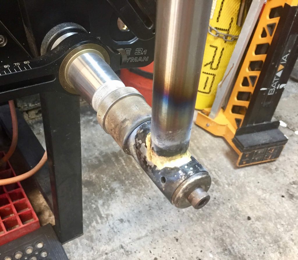
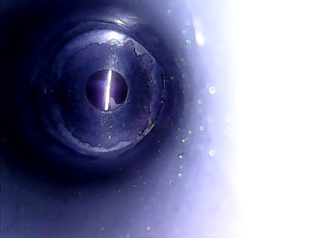
The Image above is taken looking down the seat tube with a scope camera. This new toy is quite useful in confirming penetration of brass filler when fillet brazing, and inspecting the inside of tubes for damage etc. It is limited by the fact the camera is 8mm in diameter and the quality is only as good as the price. Mine was under £30 and uses a smart phone to look at the image which keeps the price very low. Not sure I would wish to spend a lot of money on one.
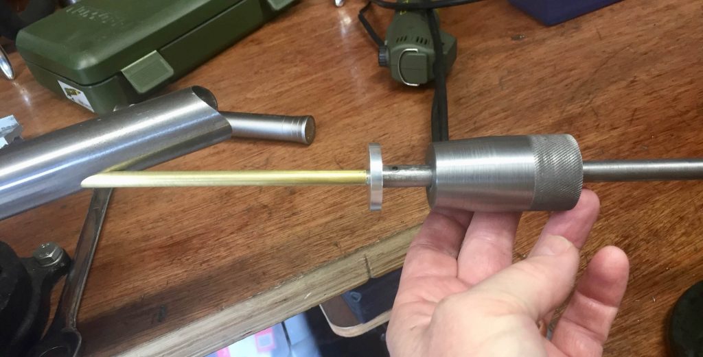
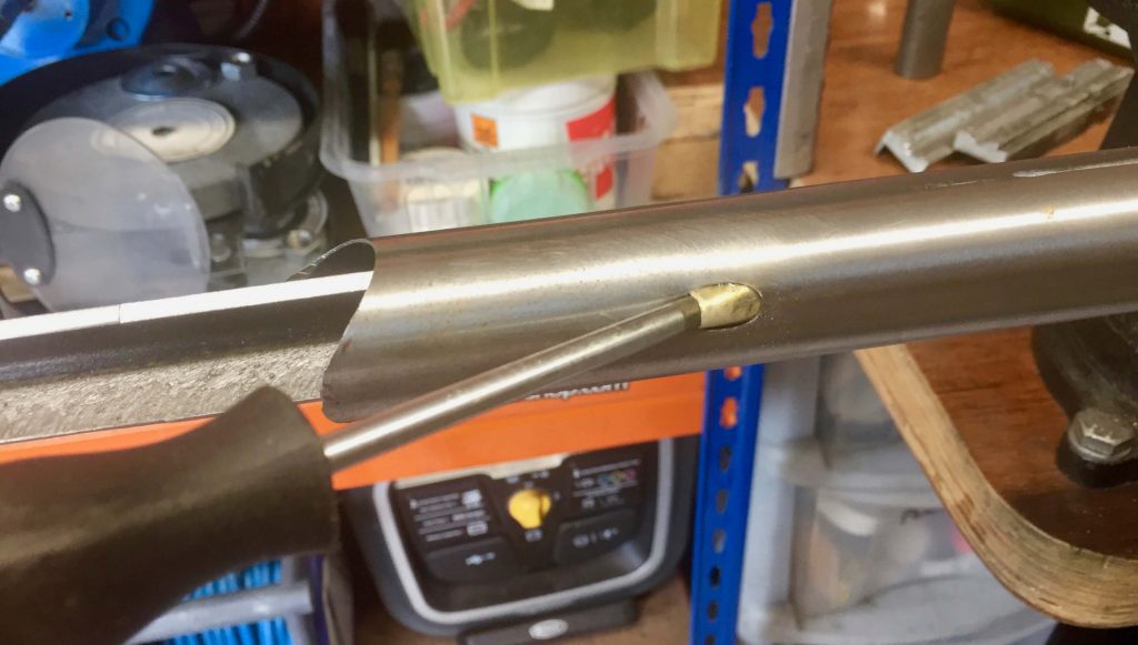
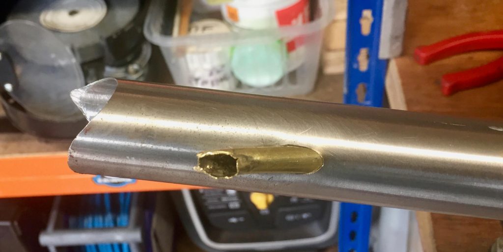
The last thing to do before final brazing is to fit the internal brass tube for top tube brake cable routing if you plan to do this. As usual I make things hard for myself and route the cable across the tube. This proved particularly difficult this time and I have to admit that by the time I had completed the frame I had use 3 brass tubes! I will be updating my post on internal top tube routing to reflect new things I have tried and will be posting the disasters from this episode in the Mea Culpa section of the website.
I used my home made slide hammer to insert the tube, which did work very well. I also used the mill to drill and elongate the hole for insertion which ends up twice as long as the diameter of the insertion tube i.e. 7 x 14 mm approx.

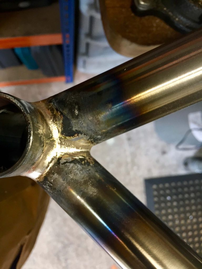
Whilst brazing order may vary I usually continue with the down tube / head tube joint, followed by the whole bottom bracket, rear dropouts, then top tube and lastly seat stays. Then followed the smoothing of all the joints, initially with a carbide burr, followed by filing and emery cloth strips.
The photographs below show the attachment of the rear dropouts to the chain stays. I placed a ring of silver in the tube then inserted the dropout with a second ring of silver inserted in the groove around the connecting section. I find 1.5 mm diameter rod and making sure the ring of rod is in good contact with the tube itself essential to ensure the rod melts. Otherwise you will end up with a bit of rod rattling around in the tube afterwards! Also heat up with the jig vertical.
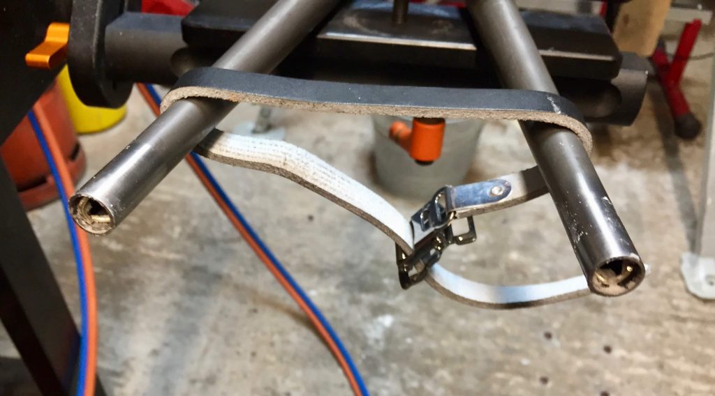
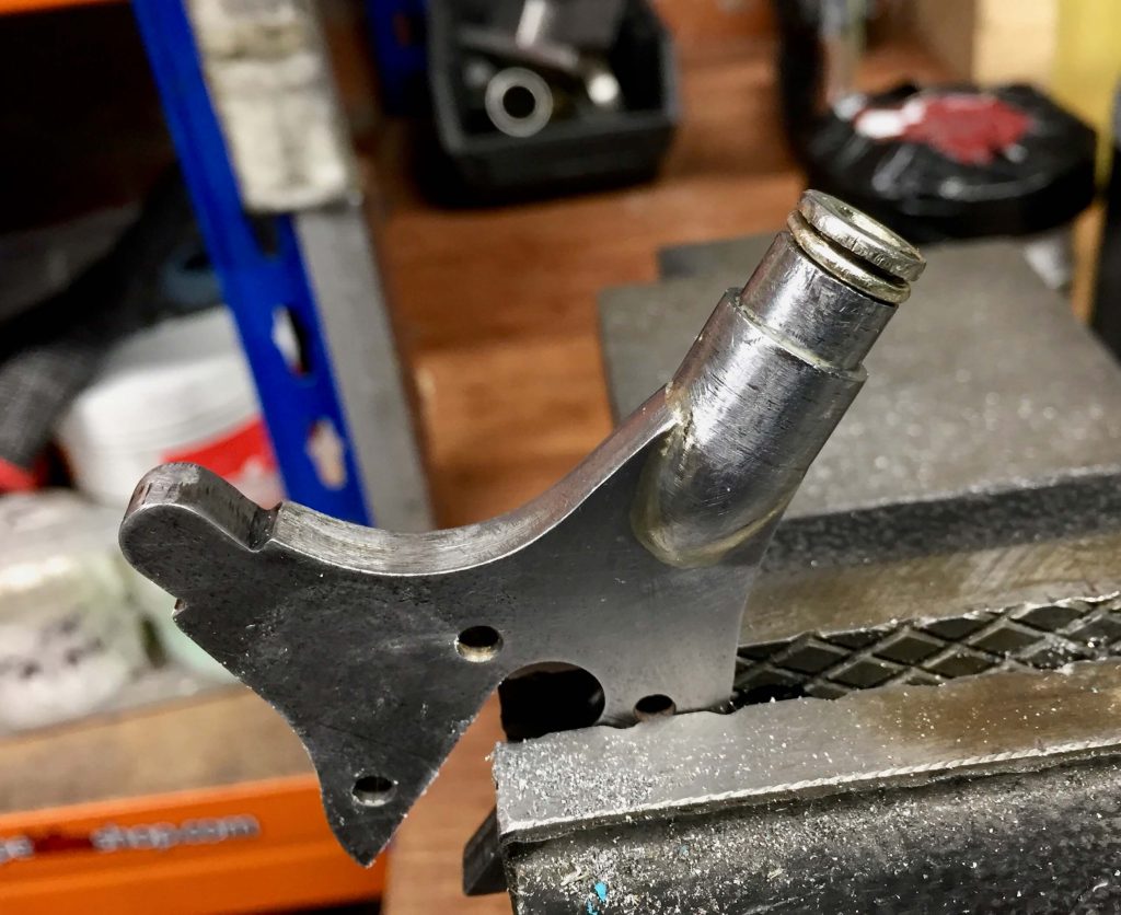
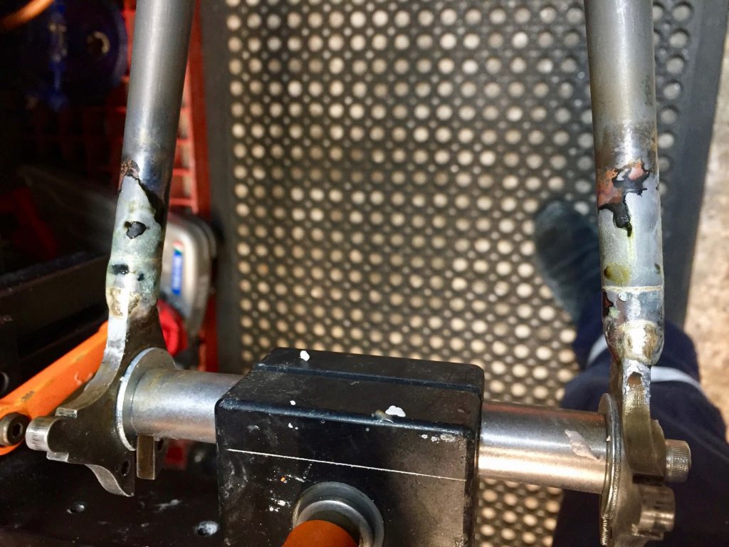
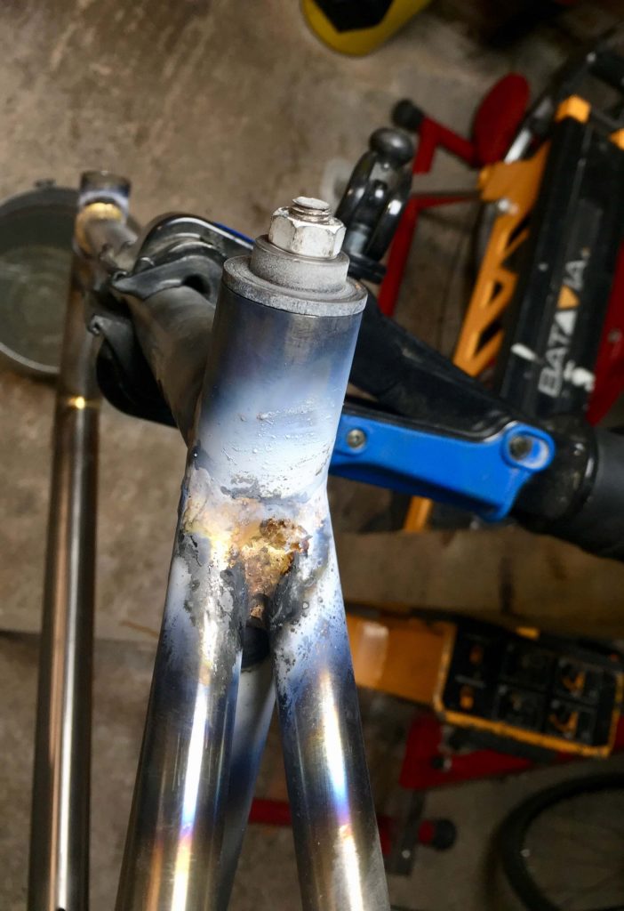
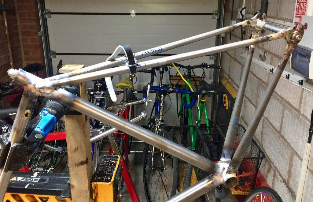
The subsequent pictures show the stainless steel head rings, seat collar and brake bridge to finish the frame all silver brazed on. A chain stay bridge was also added from scrap tube and fitted with a bottle boss for an m5 mudguard attachment point. The brake bridge was also tapped m5 underneath for the mudguards if required. Mudguard eyes also were added to the rear dropouts. Note the washers on the inside of the dropouts to compensate for the face plates which will be added, to keep the spacing correct during the build.
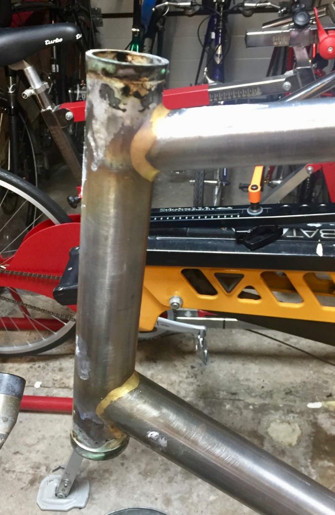
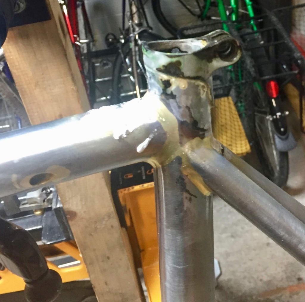
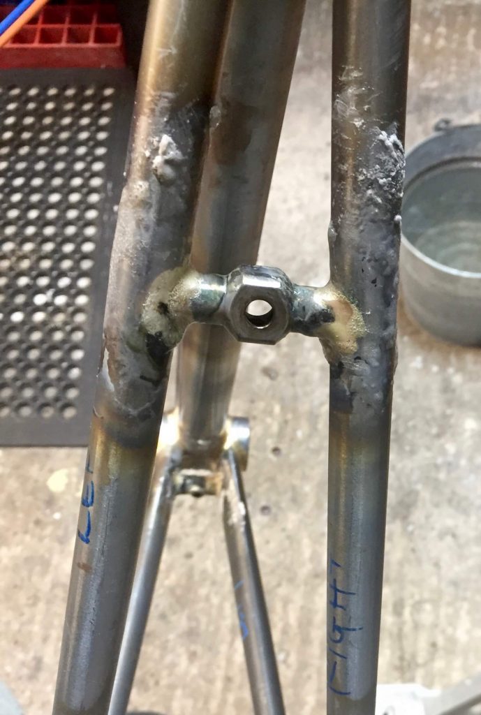
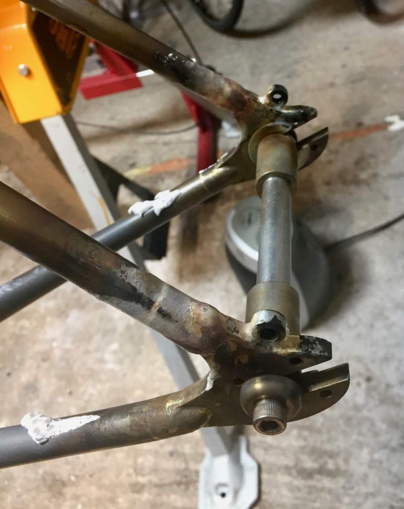
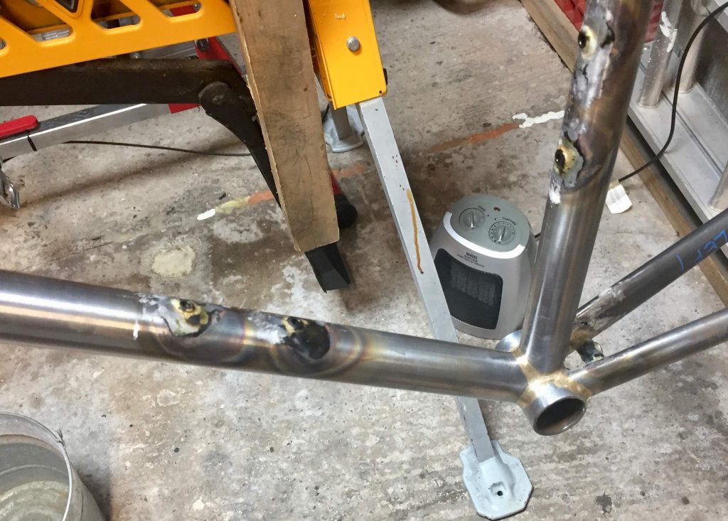
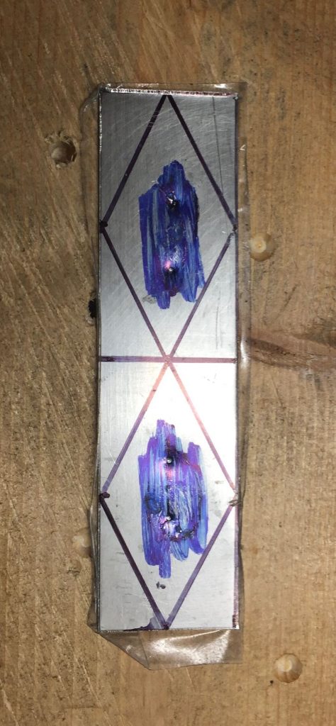
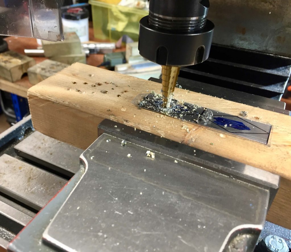
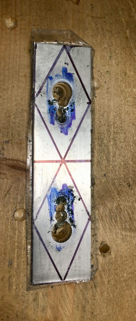
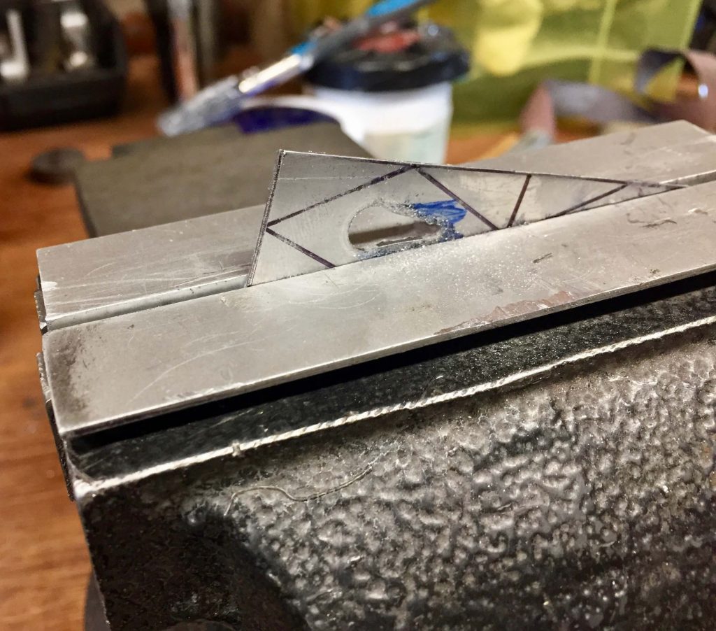
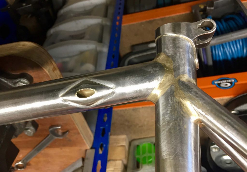
The very last thing I did before cleaning up and polishing this frame was to fit the reinforcements around the internal brake cable openings. To keep them flat I decided to make some simple diamond shapes, cut with tin snips from 0.5 mm 304 stainless steel sheet. These were first marked out and the relevant holes drilled with a step drill (most suitable for sheet materials). This was done with the sheet stuck to a piece of wood with double sided tape. After cutting and filing they were tapped into shape on a bit of scrap tube then silver soldered over the holes. This proved to be the WRONG thing to do and I have added the ensuing events to the MEA CULPA section of the website. I was able to remediate the ensuing issue but my STRONG recommendation is that if you are going to add flat reinforcements like this over internally tubed brake or gear cabe holes, do so BEFORE inserting the tube
The frame is now with the painter. I will post a photograph of the finished result in due course.