
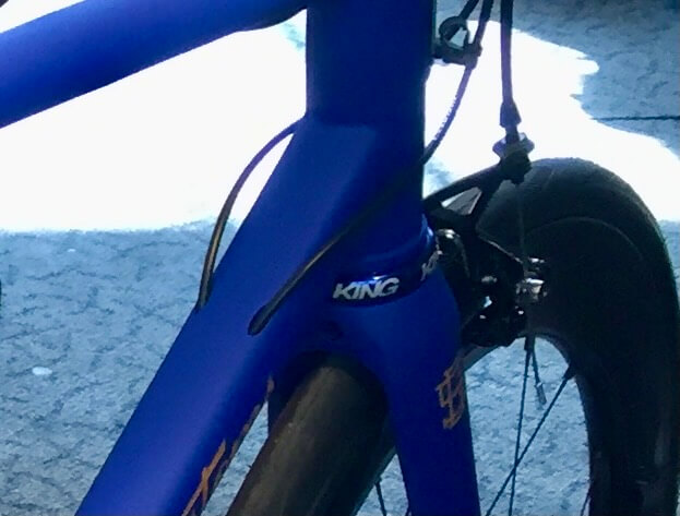
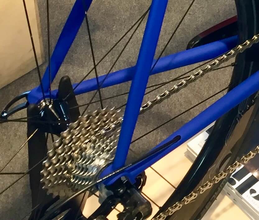
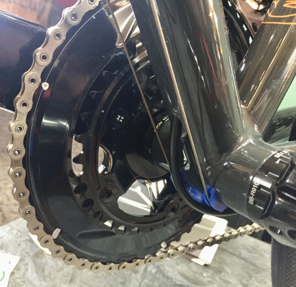
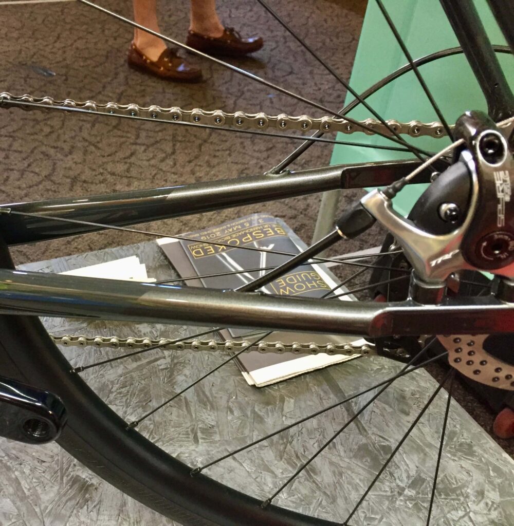
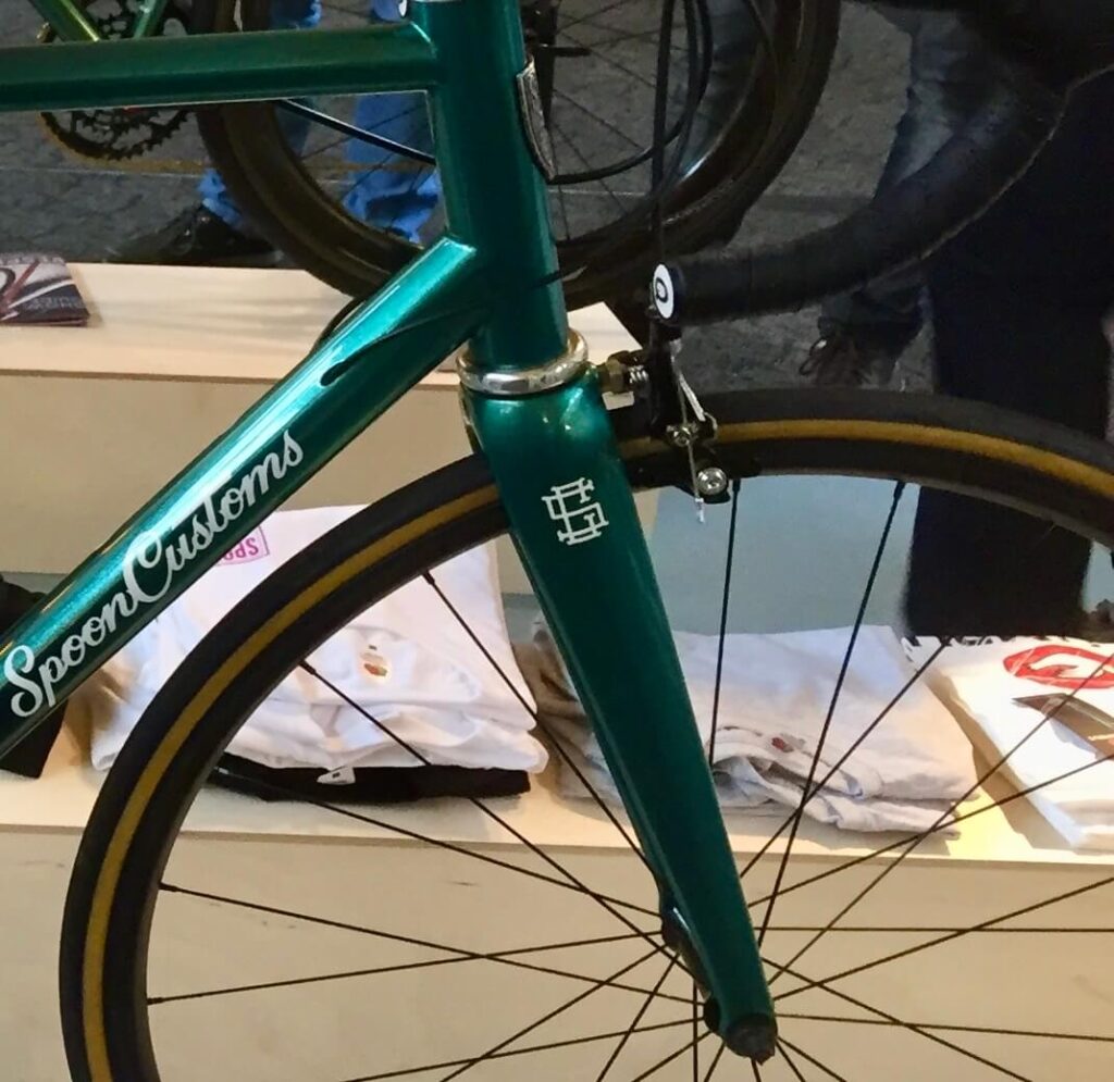
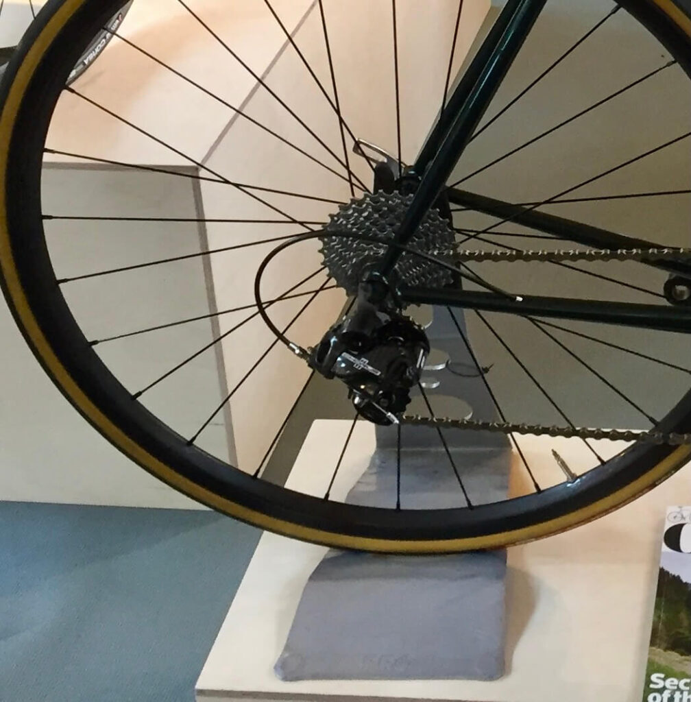
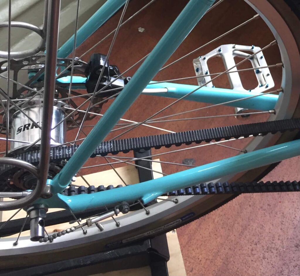
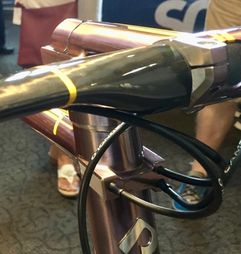
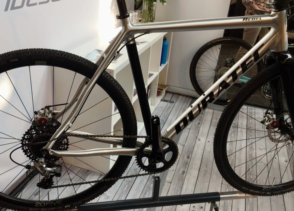
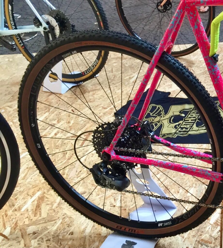
There are many different methods of routing gear cables internally. Routing the cable initially into the top of the down tube seems to be common, but I have seen examples of entry into the head tube, which for me is a step too far. Some exit the cable at the lower end of the down tube and re-enter the underside of the chain stay. Similarly some exit the chain stay near the dropout for final connection to the rear derailleur. I have problems with all of these. I am not at all keen on drilling large holes in the thin chain stays, at either end, though I guess reinforcement of these areas may help. I also do not like the appearance of cables exposed under the bottom bracket. As such my idea of full internal routing is directly through the bottom bracket and drive side chain stay, to exit through the rear dropout. For the front derailleur I want to exit at the rear of the bottom bracket. The examples shown below all appeared at various Bespoke Bike shows, where internal routing is abundant and the exit route from the chain stay is the favoured one. I can see why this is, in that in order to get clearance from the rear axle you need a particular style of dropout. On one example the rear derailleur cable exits the seat stay so it makes me wonder if in fact this is a wire. I have tried to show only cables (gear and brake, rather than electrical) on steel bikes. I obviously neglected to look under the bottom brackets of these bikes to see how they have addressed the issue of passing through or underneath it. However I have come to the conclusion that an oversize bottom bracket is the best way to address this, hence my decision to use a T47 bottom bracket for my project. The only downside to this is that the bottom bracket has to be removed to replace the cables, which I only consider a minor inconvenience.




This project was completed on the Ladies Winter Road Bike, subject of a previous post. I used a home made T47 stainless bottom bracket and a 34.9 mm Reynolds 853 down tube and Reynolds 953 chain stays. the dropouts were 953 stainless obtained from Ceeway. These fitted the chain stays, which I already had in, but I thought suitable to modify so the cable runs right out at the end. This was the first task.
For the routing tube I used 6 mm outside diameter thin walled (0.45 mm) brass tube which I obtained in 1 metre lengths. It may available from many metal suppliers but I usually get mine from Macc Models which can also supply 7 mm tube for brake cables. Although most builders seem to leave their entry holes flush I prefer to cover mine with caps. The ones I use are designed for 7 mm tube but can be back filled after fitting the 6 mm tube.
I drilled out the vent hole in the drive side chain stay dropout, in the end to 6.5 mm. I tried to angle it, as much as possible, upwards and position it as far out in the socket as possible, but there is very little room for manoeuvre.
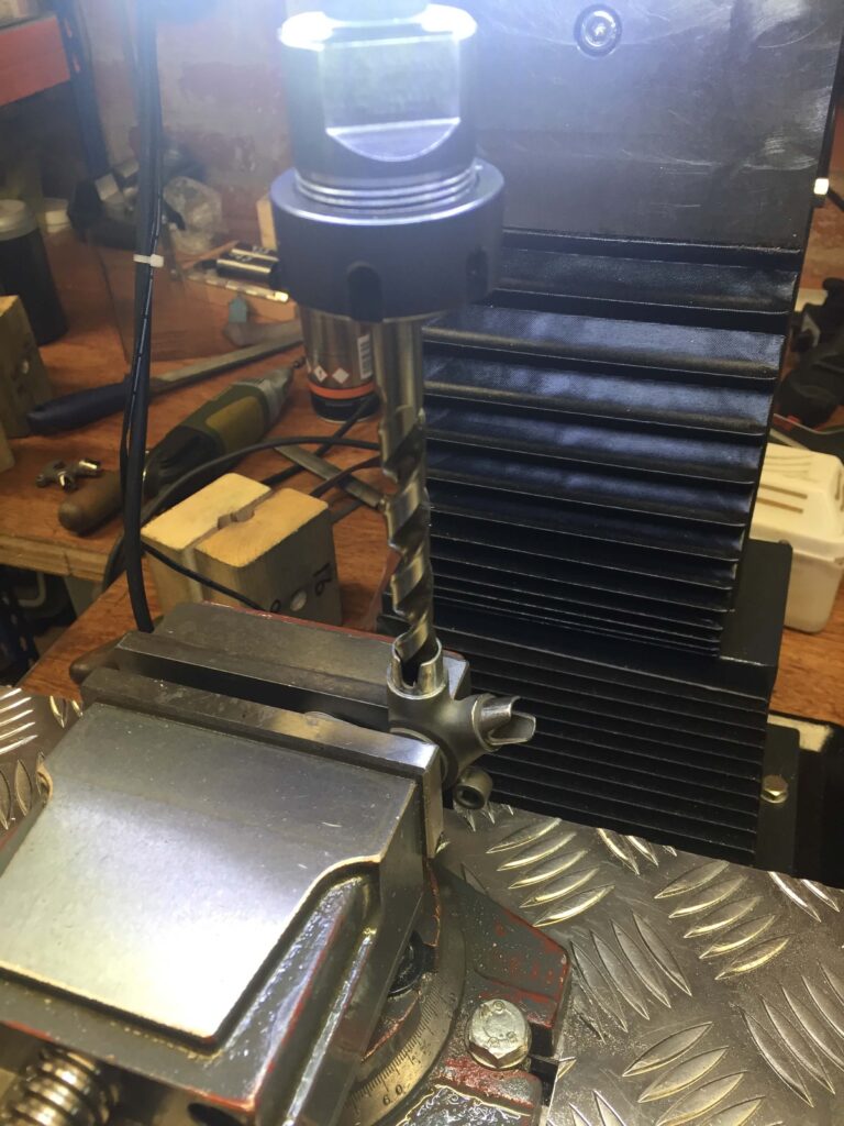
Initially you can use a drill the same size as the socket to make sure the dropout is central 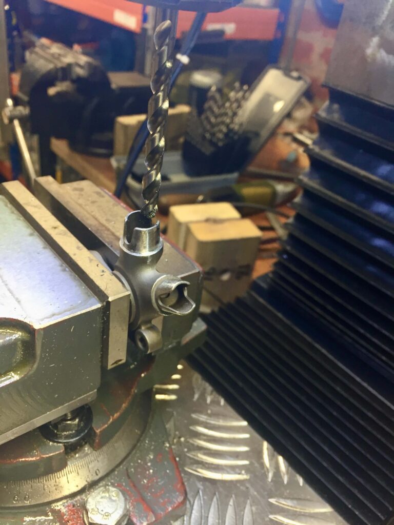
Then in a mill and with the correct size drill you are able to wind the dropout away from the centre an exact amount 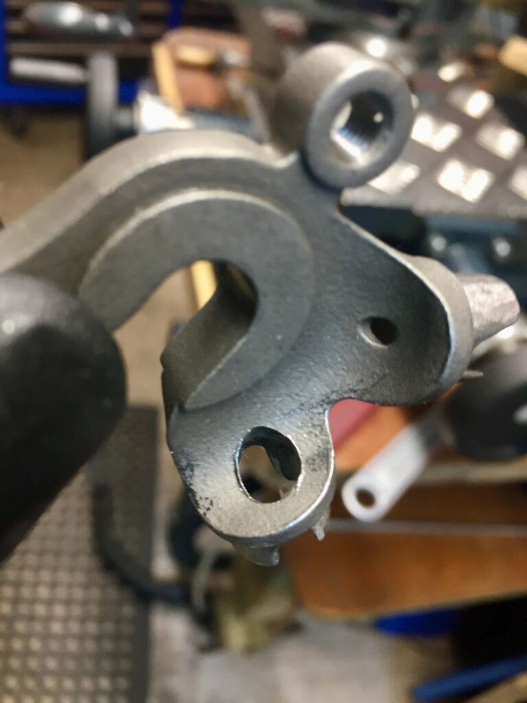
Hole slightly angled upwards
The next part of the process was to drill all the other holes for routing. Starting with the bottom bracket shell; one for the drive side chain stay, one for front derailleur exit and at the front one for each of the front and rear derailleurs. I used the correct size drills and try to position the holes to provide the least tortuous route through the bottom bracket i.e trying to angle them where possible and using a small file to finish off . Even with the larger diameter bracket shell this is not easy. I came very close to the down tube itself with the holes, so careful initial marking of the tube positions before commencing is vital. Other holes that appear in the pictures are simple vent holes
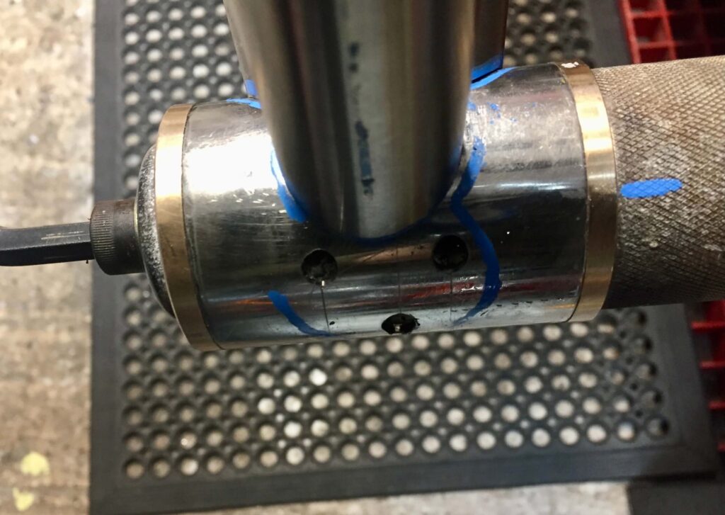
Front of bottom bracket shell 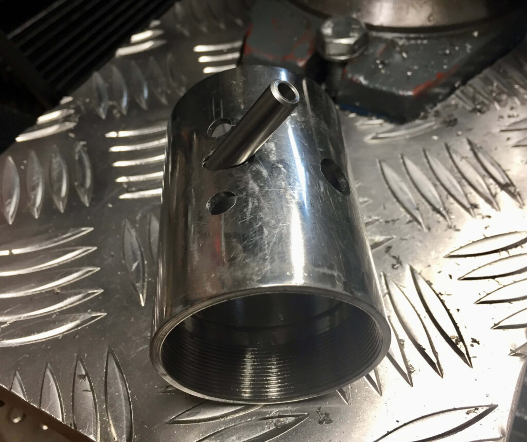
Rear of bottom bracket shell with front derailleur cable guide angled vertically and slightly pointing to the Right 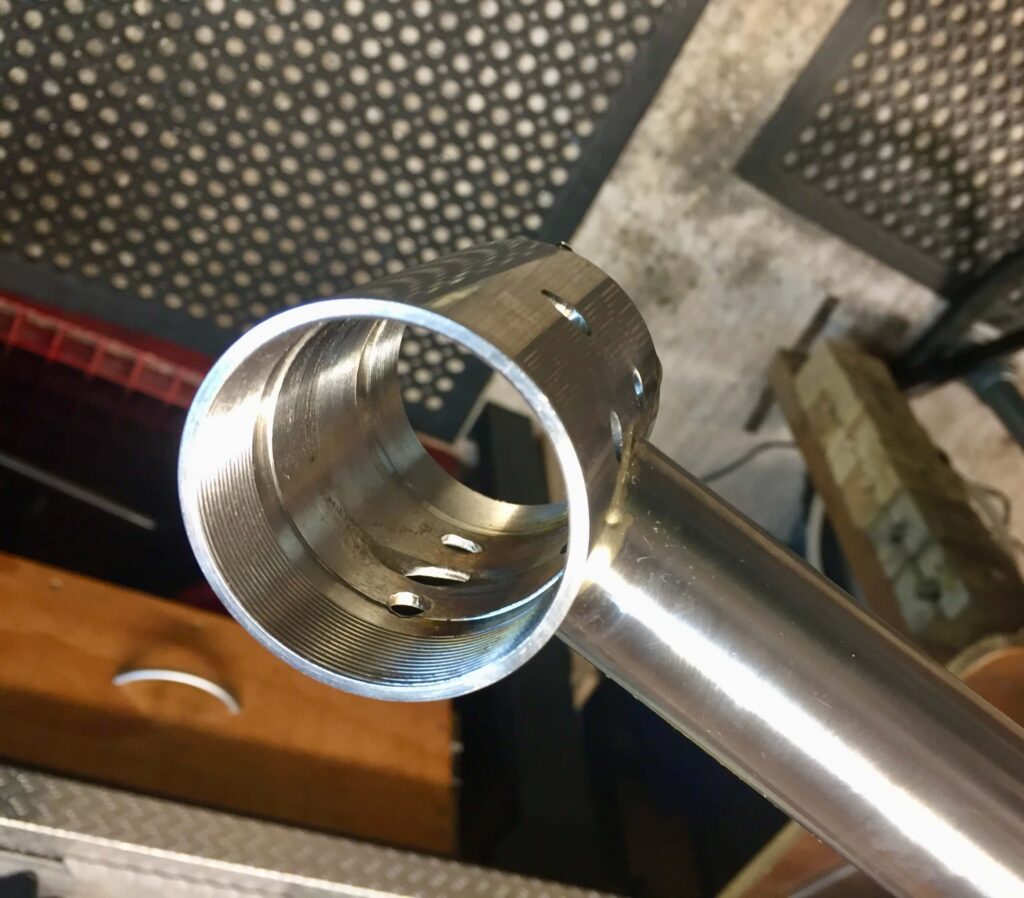
Holes in correct place after fixing the seat tube 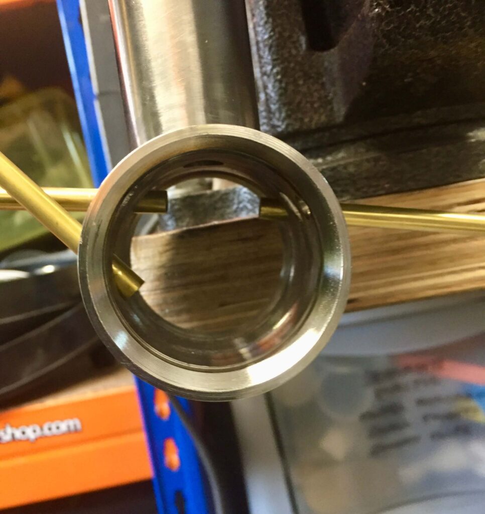
This shows the angles I hope to be able to fix the tubes at. The front derailleur cable will run along the bottom of the shell and the rear derailleur over the top.
Given the way the tubes lined up the shortest distance for the rear derailleur was over the top of the bottom bracket, and for the front derailleur the smoothest course was along the bottom of the shell. By bending the ends of the tubes a little I should be able to smooth out the cable route through the shell a little more. The front derailleur cable will exit into a tubular stainless steel cable stop. These are 7 mm in diameter with a 4 mm bore, so are a nice firm fit for the gear cable. They are sold by Ceeway as end stops for internal bare wire cable routing but serve this purpose very well.
The next step is to drill holes through the upper end of the already mitred down tube in your favoured position. As usual with thin walled tubes it is best to do this fixed in a vice, drill press or mill. I tend to use a milling cutter as you can elongate the hole easily. Next assemble the frame after fixing the bottom bracket to the seat tube in the correct position. The brass tubes for the down tube are cut to the appropriate length and a slight bend placed in the top, use a small tube bender or by-hand with a cable in situ. It should be easy to introduce the tube from the bottom and through the holes in the upper end of down tube. Then pre-assemble the frame to check everything fits, this includes sliding the brass tubes through the holes in the bottom bracket. Mark the bottom of one so you know which is which, as the can get twisted. You can then flux up the down tube joints and braze the down tube in place.
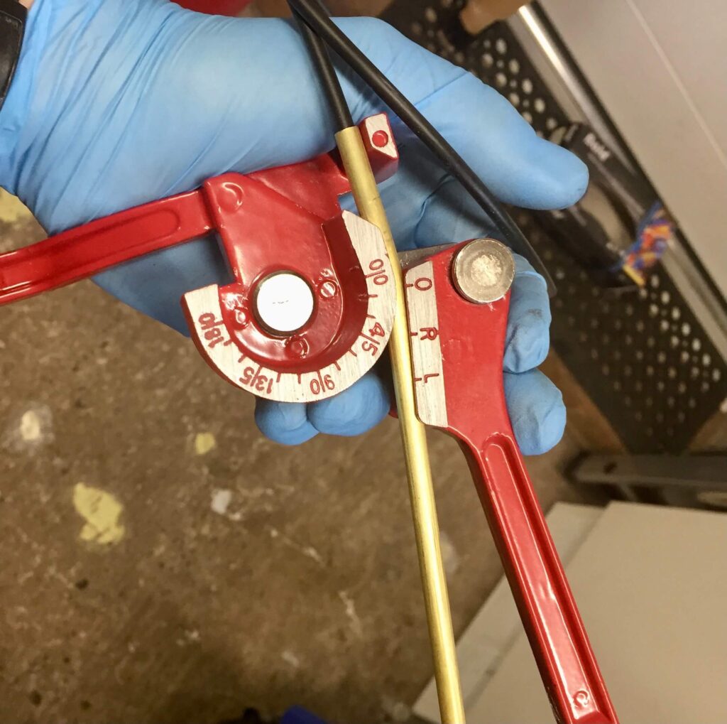
Slight bend in upper end of brass tube 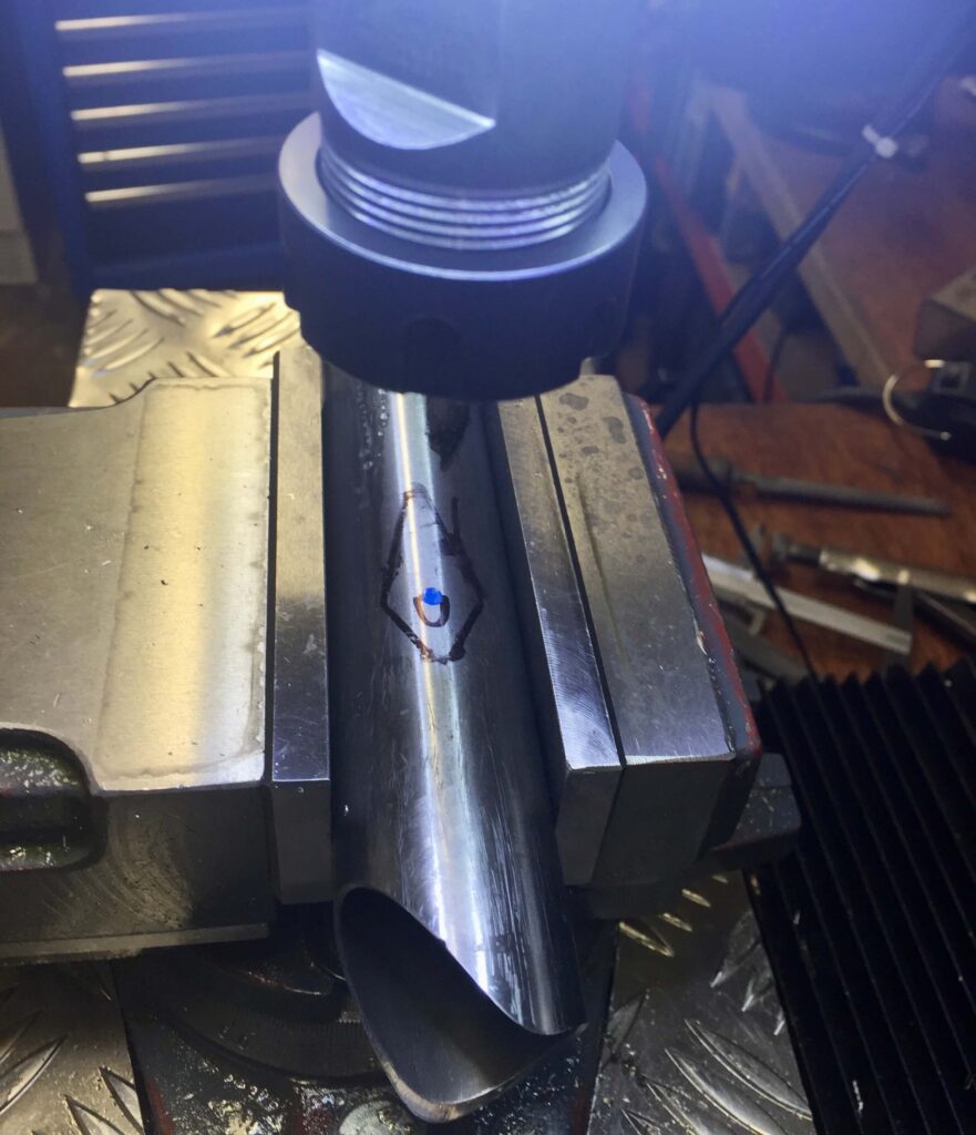
Cable entry marked and cut 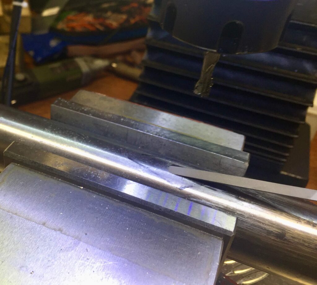
Filing at an angle to smooth the entry hole 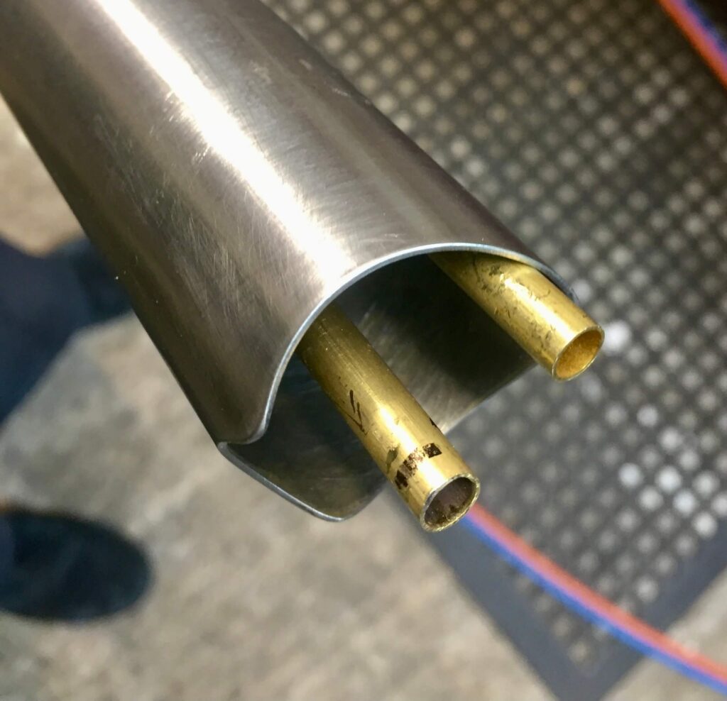
Brass tubes need to have just enough length to penetrate the bottom bracket shell 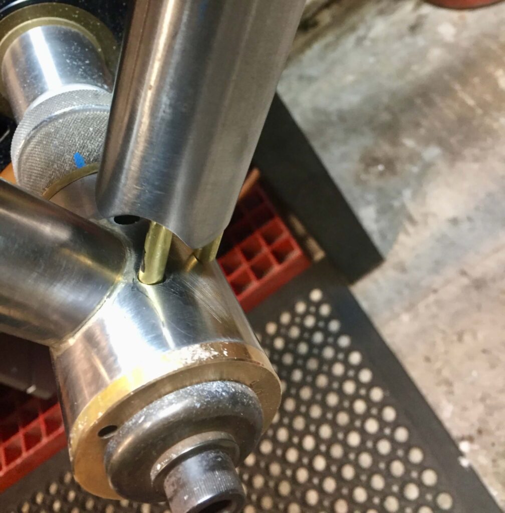
Slotting the down tube into the bottom bracket shell 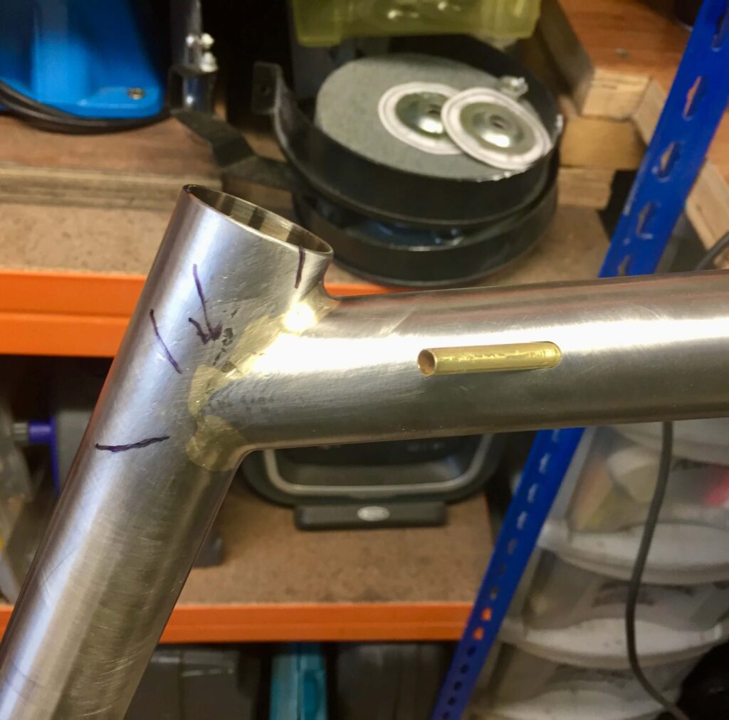
Brass tubes now need fixing
After brazing in the down tube the brass tubes can be soldered in at the top with silver, and the caps added before filing away the surplus. The frame then needs removing from the jig or fixture to access the inside so the lower ends of the brass tubes can be fluxed and silver soldered into position.
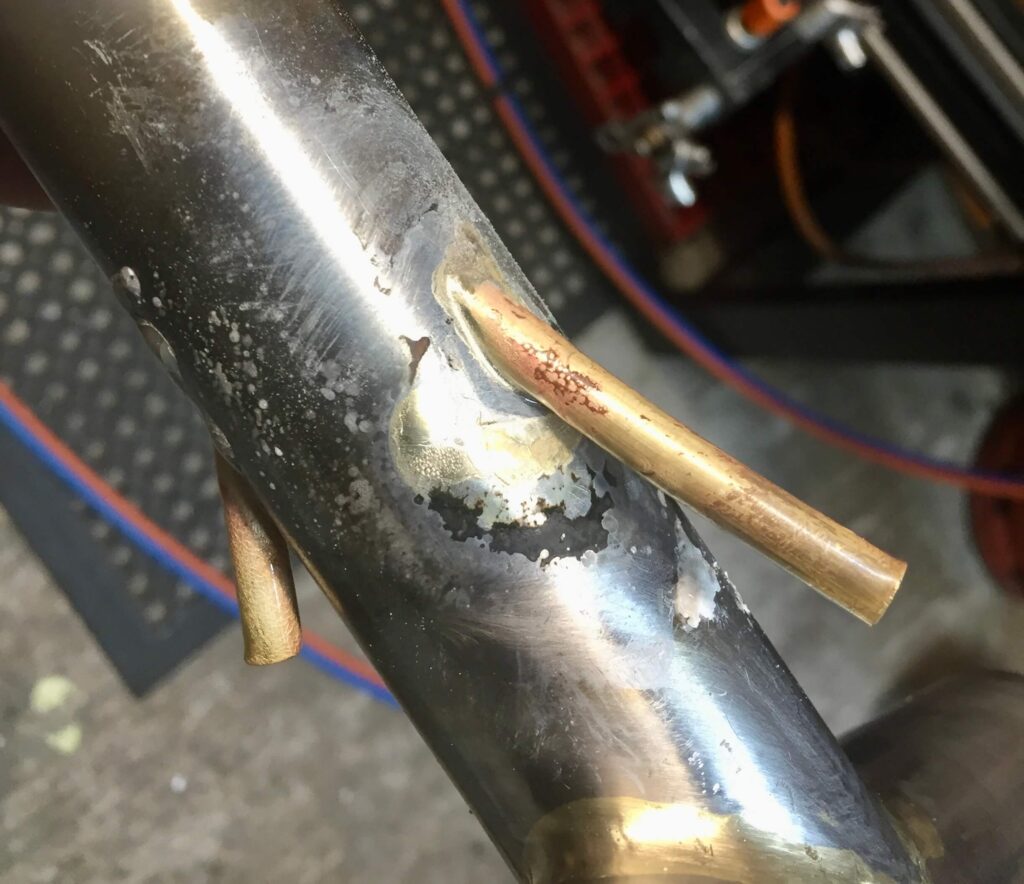
Fixing in the top end of the cable guides 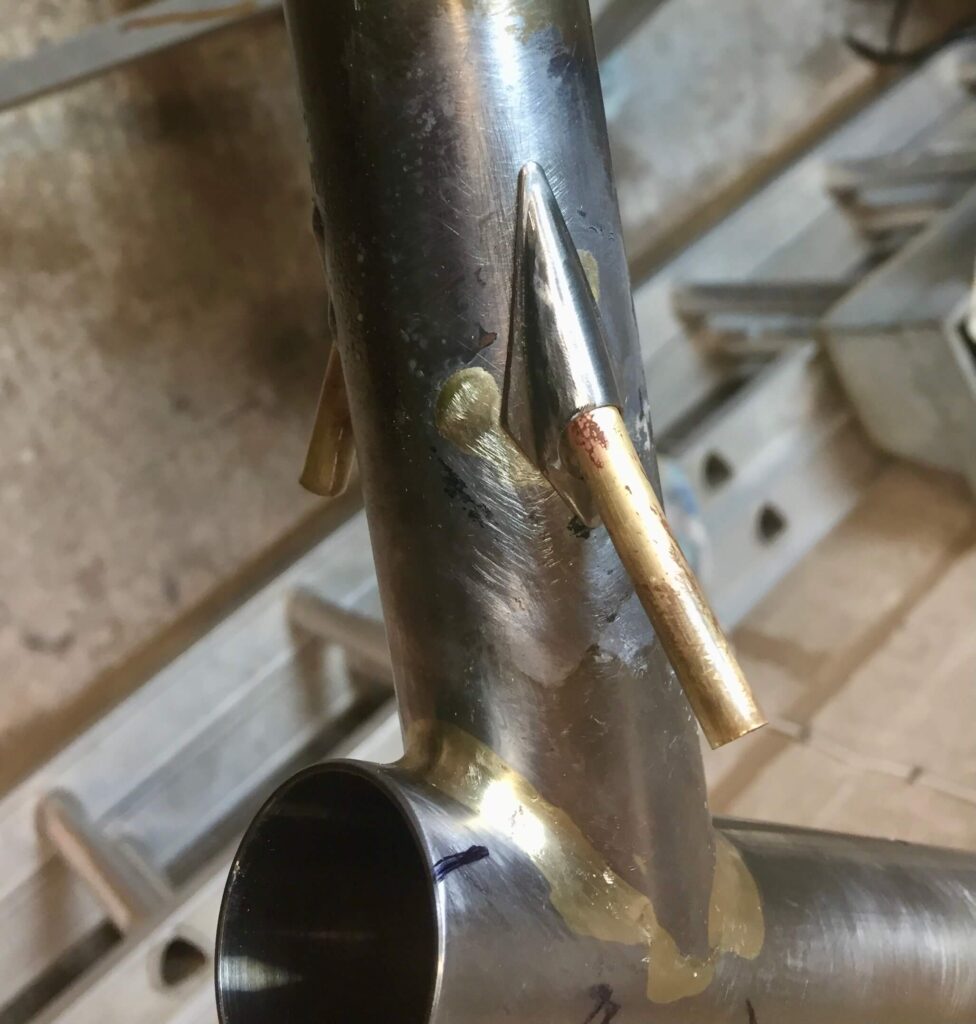
Adding the covers 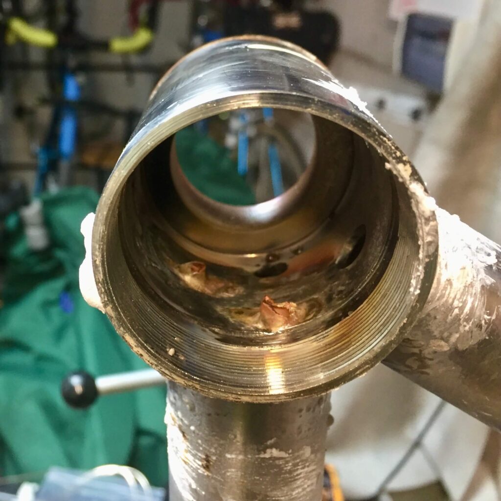
Lower ends of the cable guides soldered in.
The tendency is, that if you are going to do internal routing for the gears, you are going to do the rear brake cable as well, which was my next step. My methods are described elsewhere but shown below.
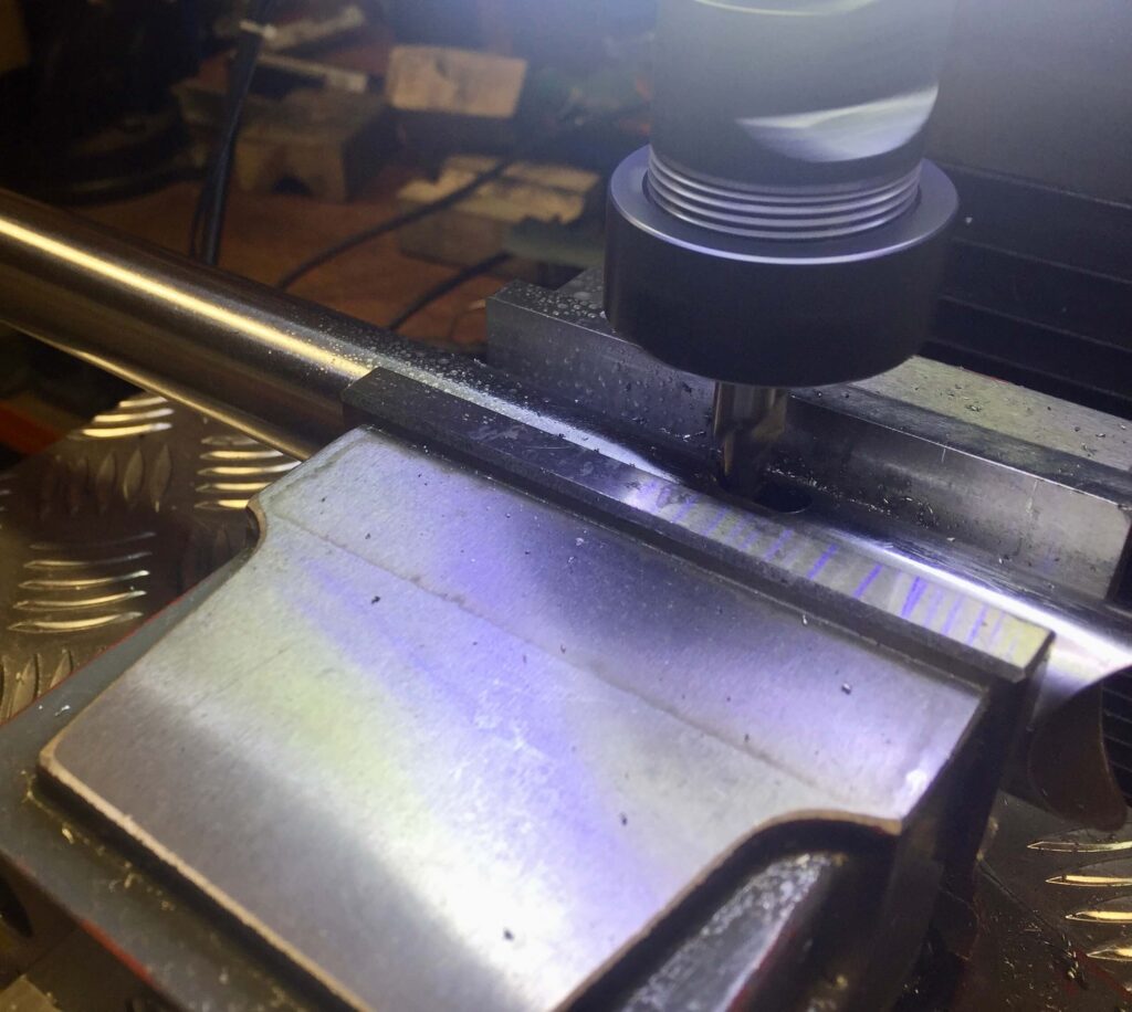
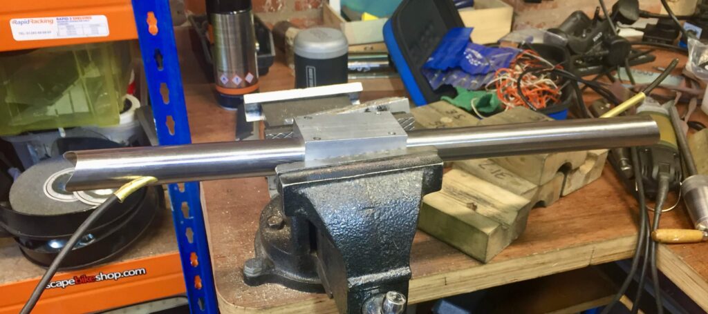

The next step is to attach the chain stays to the bottom bracket shell. Once this is done another 6 mm brass tube can be inserted through the drive side chain stay into the bottom bracket shell, with a little gentle bending at that end, The dropouts are added to the stays with enough tube poking out and the bracket end of the brass tube silver soldered in as before. The rear dropouts can now be brazed into place followed by securing the dropout end of the brass tube with silver solder and smoothing off to finish the job.

The last piece of the puzzle is to silver solder the front derailleur cable guide through the hole in the back of the bottom bracket shell. I have hopefully angled this correctly towards the front derailleur lever clamp bolt, which was only done by eye. Whilst soldering it into place I inserted a thin steel rod down it and strapped it to the seat tube so it would not move.
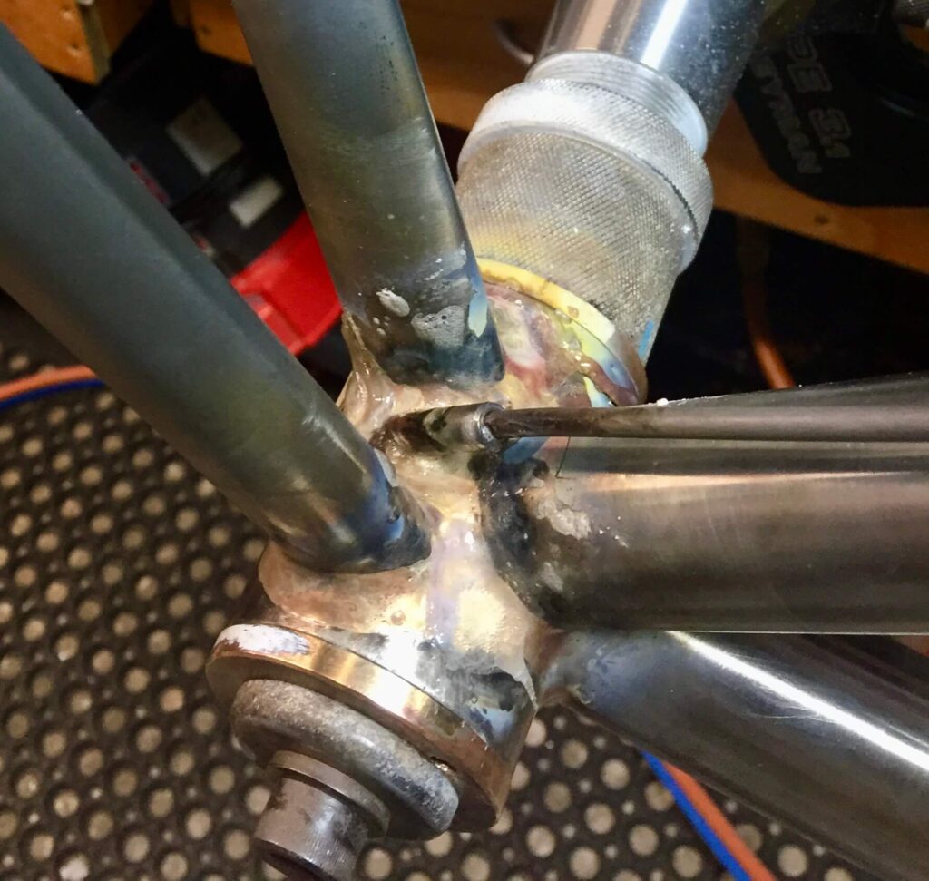

The Finished Frame
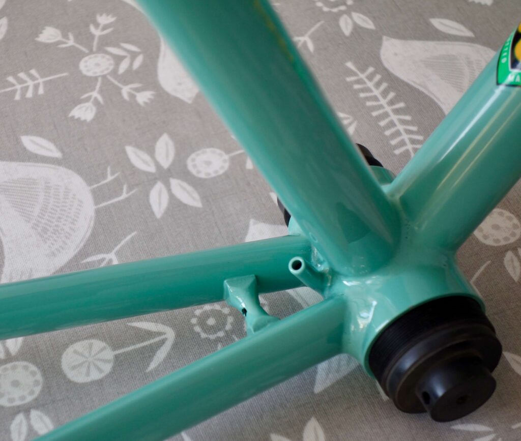
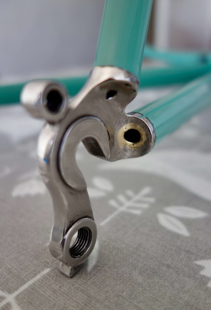
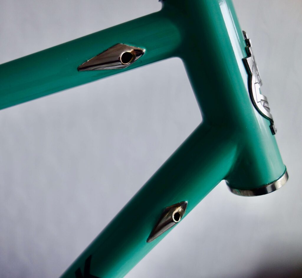
Cables in Situ
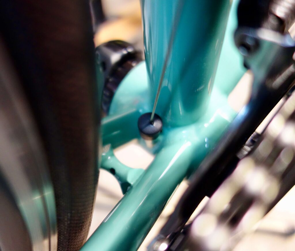
A rubber cap re-purposed 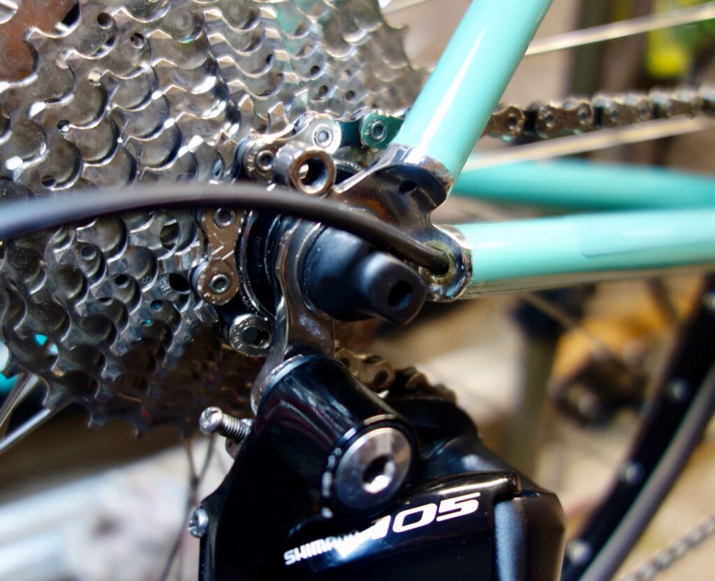
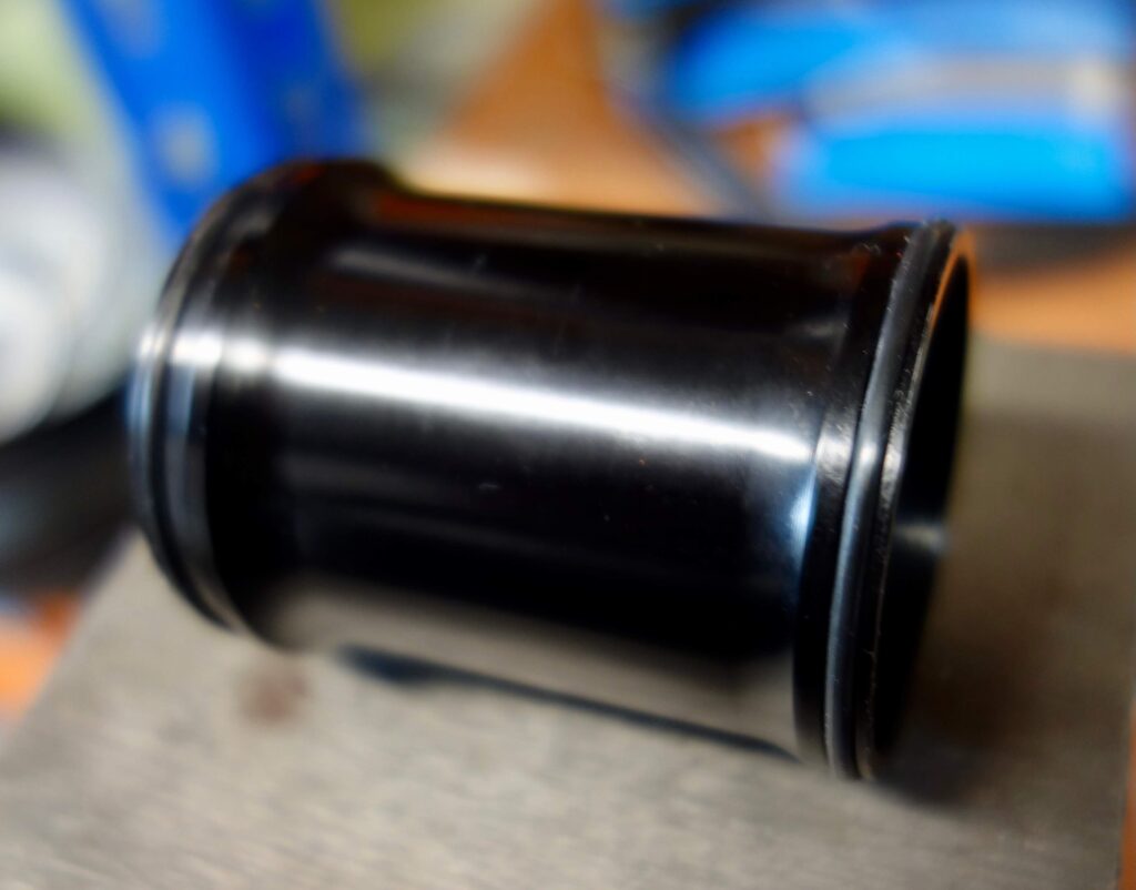
Dust sleeve too big to fit 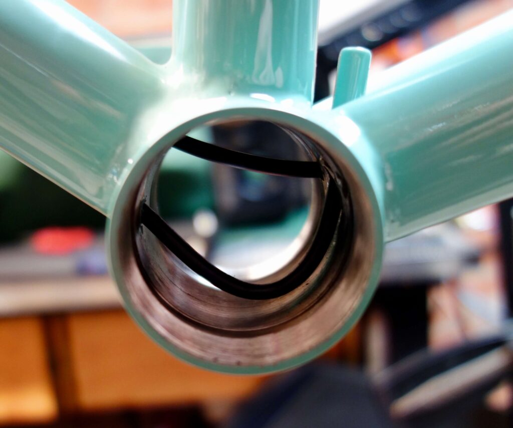
More flexible cables would be helpful 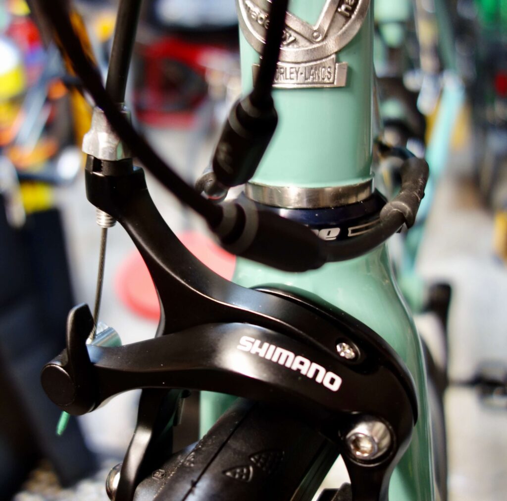
Cable adjusters essential
A rubber cap on the front derailleur cable guide reduces risk of water getting into the bottom bracket and cable. Important because as you can see cables are not as flexible as you would like them to be. The clearance for the axle was enough but it was impossible to get the bottom bracket sleeve in so I dispensed with it.
I have seen T47 bottom brackets with a sleeve with a narrowed centre portion, but as you might guess at present – out of stock. I originally considered putting cable guides inside the bottom bracket, but I can now see it would still not be possible to bend the cables sufficiently to go through them. Cable adjusters on the cables are also essential.
In the final analysis the project was a success, and gear shifting functions normally.